Detecting method for flexural fatigue crack initiation process of submarine pipeline
A technology for fatigue cracks and submarine pipelines, applied in the direction of applying stable shear force to test the strength of materials, measuring devices, instruments, etc., can solve the problems of prone to accidents and high probability of failure of pressure pipelines
- Summary
- Abstract
- Description
- Claims
- Application Information
AI Technical Summary
Problems solved by technology
Method used
Image
Examples
Embodiment 1
[0049] Embodiment 1 detection method
[0050] The embodiment of the present invention provides a detection method for the initiation process of the bending fatigue crack of the submarine pipeline. The detection method is as follows:
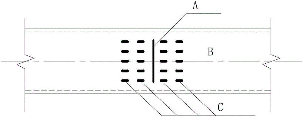
[0051] A part of the oil pipeline is taken as the pipeline test piece, and the middle position of the lower end surface of the pipeline test piece is provided with several rows of axisymmetric strain gauges along the axial direction, and the strain gauges in each row are arranged in a row along the radial direction (see figure 1 ), each of the strain gauges is arranged along the axial direction of the pipeline test piece, and is used to detect the axial tensile strain of the pipeline test piece under the action of bending moment; figure 1 Among them, A is the crack, B is the bottom of the pipe test piece, and C is the strain gauge.
[0052] Place the pipe test piece with strain gauges on the platform of the fatigue pressure mechanism, the two en...
Embodiment 2
[0067] Embodiment 2 detection device
[0068] see Figure 6 , the embodiment of the present invention provides a detection device for the initiation process of a subsea pipeline bending fatigue crack that can implement the detection method in Embodiment 1, including a base 31, two support frames 32 symmetrically arranged on the base 31, and two The fatigue pressure mechanism 38 on the platform 31; the pipe test piece 36 is arranged on the support frame 32, and the two ends of the pipe test piece 36 are fixedly connected with a supporting end plate 35, and the middle part of the pipe test piece 36 is symmetrically arranged with two vertical loading plates. plate 41, the pipeline test piece 41 passes through the middle part of the vertical loading plate 41, and a horizontal plate 40 is arranged on the upper end surface of the two vertical loading plates 41; the lower end surface of the support end plate 35 is placed on the upper end surface of the support frame 32; The lower en...
Embodiment 3
[0075] Embodiment 3 Positioning device for welding
[0076] In order to obtain accurate detection results, the embodiment of the present invention provides a positioning device for welding pipe test pieces, see Figure 7-Figure 10 , the positioning device includes a platform 1 and a mobile vehicle 28 that is movable on the platform 1, an intermediate plate 25 is arranged on the platform 1, and two arc-shaped support frames 16 are symmetrically arranged on the mobile vehicle 28, which are located on the outside of the arc-shaped support frame 16. Two fixed splints 8 with arc-shaped notches are symmetrically arranged on the platform 1, and two movable splints 9 with arc-shaped notches are symmetrically arranged on the outer platform 1 of the fixed splint 8, and are symmetrically located on the outer platform 1 of the movable splint 9 There are two movable positioning plates 4; the arc-shaped support frame 16, the fixed splint 8, the movable splint 9 and the movable positioning p...
PUM
 Abstract
Description
Claims
Application Information
 - R&D
- Intellectual Property
- Life Sciences
- Materials
- Tech Scout
- Unparalleled Data Quality
- Higher Quality Content
- 60% Fewer Hallucinations
Browse by: Latest US Patents, China's latest patents, Technical Efficacy Thesaurus, Application Domain, Technology Topic, Popular Technical Reports.
© 2025 PatSnap. All rights reserved.Legal|Privacy policy|Modern Slavery Act Transparency Statement|Sitemap|About US| Contact US: help@patsnap.com


