Temperature monitoring device and method, information processing program and recording medium

A monitoring device and program technology, applied in the direction of program control, measuring device, electrical program control, etc., can solve the problems of not considering the motor control device, unable to realize overheat protection, etc., and achieve the effect of preventing failure

Active Publication Date: 2017-09-19
ORMON CORPORATION
View PDF9 Cites 9 Cited by
  • Summary
  • Abstract
  • Description
  • Claims
  • Application Information

AI Technical Summary

Problems solved by technology

Therefore, it is impossible to realize overheating protection that takes the entirety of the motor frame and the motor control device (servo driver) into consideration.
[0008] Moreover, in the method described in Patent Documen

Method used


Image

  • Temperature monitoring device and method, information processing program and recording medium
  • Temperature monitoring device and method, information processing program and recording medium
  • Temperature monitoring device and method, information processing program and recording medium

Examples


Example Embodiment

[0074] Outline of Control System

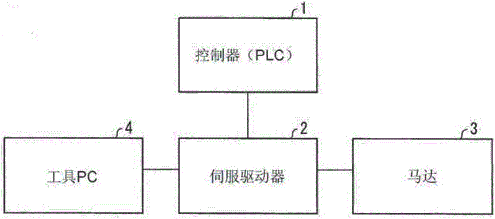
[0075] Hereinafter, the embodiments of the present invention are based on Figure 1 to Figure 5 to explain. First, refer to figure 2 The control system of the present embodiment will be described. figure 2 It is a figure which shows the outline of the control system of this embodiment. The control system uses a servo mechanism to control the action of the load device, such as figure 2 As shown, it includes a controller (Programmable Logic Controller (PLC)) 1, a servo driver (motor control device, temperature monitoring device) 2, a motor 3, and a tool (Personal Computer, PC) 4 .

[0076] The controller (PLC) 1 controls the entire system including the servo driver 2 .

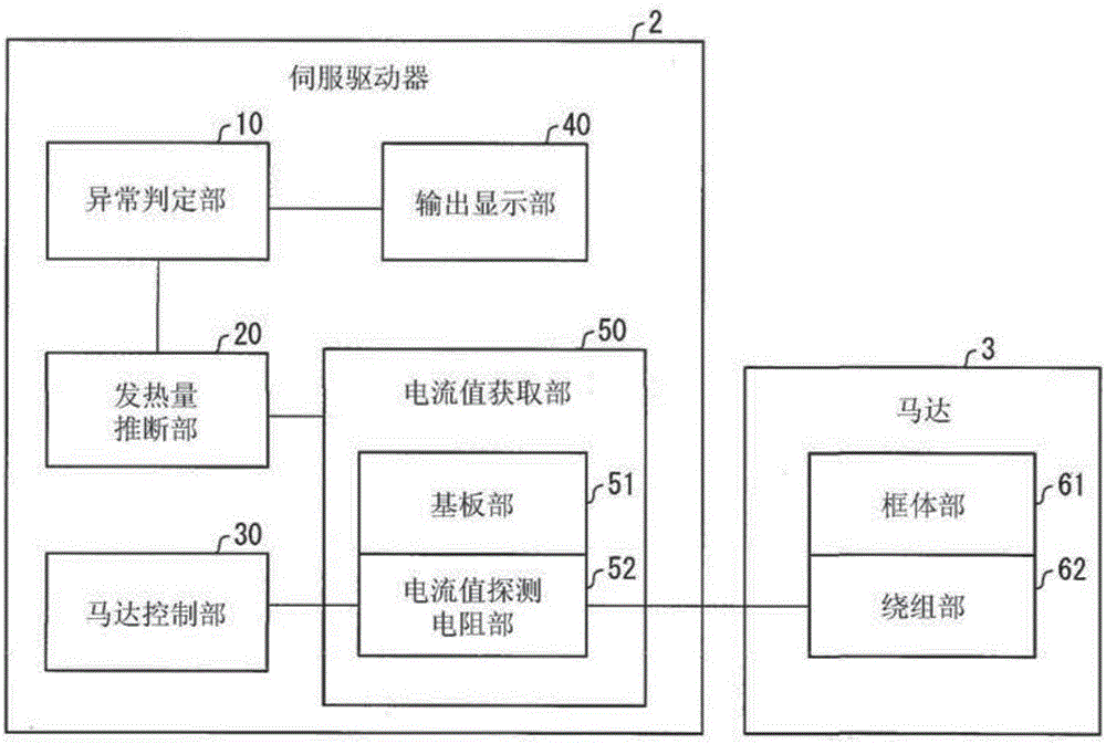
[0077] The servo driver 2 stores control parameters set and adjusted by the controller 1 or the tool PC 4 described later, and drives the motor 3 in accordance with the control parameters to operate the load device.

[0078] Furthermore, the servo driver 2 monitors th...


PUM


Abstract

The invention relates to a temperature monitoring device and method, an information processing program and a recording medium. The temperature monitoring device includes: a current value acquisition portion (50) that acquires a current value supplied for the motor; a calorific value inference portion (20) that infers a calorific value through a first thermal model indicating a relationship between the current value and a calorific value of a servo driver (2); and an anomaly judgment portion (10) that compares the calorific value with a threshold, so as to judge whether there is heating anomaly. The invention can achieve overtemperature protection of a system including a motor and a control device.

Description

technical field [0001] The present invention relates to a temperature monitoring device and the like that monitor the temperature of a motor and a motor control device that controls the motor. Background technique [0002] Conventionally, various methods have been considered for overheating protection of a motor used in a machine tool or the like and a servo driver or the like that controls the motor. For example, Patent Document 1 describes a method of detecting an electric current value applied to the motor and comparing the electric current value with a threshold value to limit the electric current value applied to the motor, thereby protecting the motor from overheating. Furthermore, Patent Document 2 describes a method of detecting a current value applied to a motor, and estimating each configuration of the motor based on a thermal model (model) representing the relationship between the current value and the heat generation / radiation of each part of the motor The heat ...

Claims


Application Information

Patent Timeline
IPC IPC(8): H02P29/64H02P29/024
CPCH02P29/027H02P29/60H02P29/666H02P29/68G01K17/00G01N25/72G05B19/18G05B2219/31455
Inventor 山脇圣牛山孝雄平尾健太郎
Owner ORMON CORPORATION
Why Eureka
Try Eureka