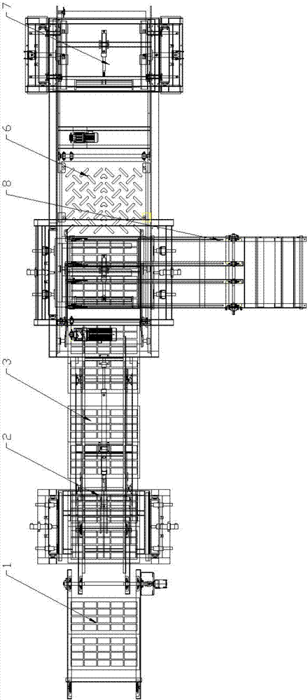
Stacking machine
A palletizer and palletizing technology, which is applied in the field of brick-making process equipment, can solve the problems of brick weight, difficulty in automatic production, and large load, and achieve the effects of less equipment consumables, saving labor costs, and low quality.
- Summary
- Abstract
- Description
- Claims
- Application Information
AI Technical Summary
Problems solved by technology
Method used
Image
Examples
Embodiment 1
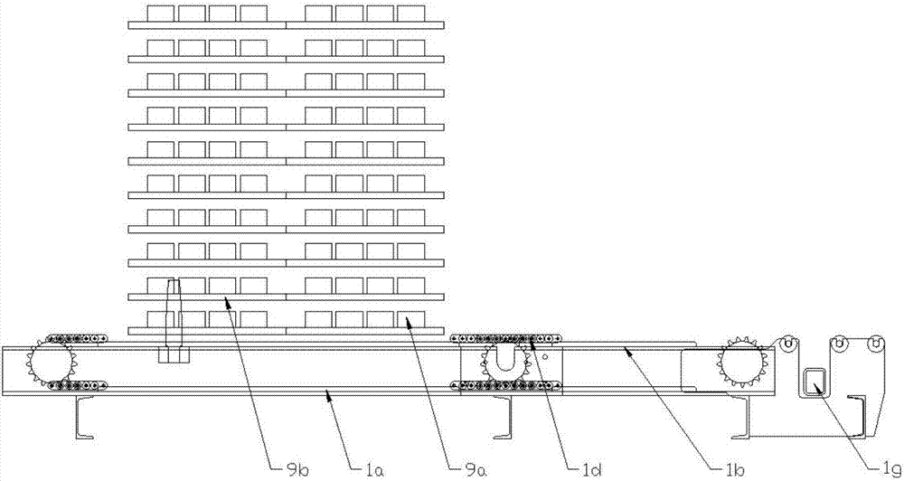
[0118] Figure 19 It is a side-view structural schematic diagram of the transport mechanism of the present invention transporting brick boards to the pallet lifter, as shown in Figure 19 as shown,
[0119] The conveying process of brick raw material 9:
[0120] 1-1. Start the feeding motor 1e;
[0121] 1-2. The feeding motor 1e is decelerated and driven through the feeding coupling 1f;
[0122] 1-3. 1d movement of the feeding chain;
[0123] 1-4. Brick board raw material 9 moves from front to back with the feeding chain 1d;
[0124] 1-5. Brick board raw material 9 moves from driving feeding slideway 1a to driving feeding slideway 1b
[0125] 1-6. Brick board raw material 9 moves to the end of transmission feeding slideway 1b;
[0126] 1-7. The feeding sensor 1g senses the arrival of the brick raw material 9;
[0127] 1-8. The feeding motor 1e stops working.
[0128] In this embodiment, the brick and board raw materials 9 are stacked together, which is one of the proce...
Embodiment 2
[0132] Brick Raw Material 9 Improvement:
[0133] Figure 20 It is a schematic diagram of the side view structure of the lifting board machine of the present invention lifting the brick board raw materials; as Figure 20 Shown, on the basis of embodiment 1:
[0134] 2-1. The composite lift cylinder 2b starts;
[0135] 2-2. The lifting plate 2c is raised through the transmission of the lifting chain 2d;
[0136] 2-3. Brick board raw material 9 rises with the lifting pallet 2c;
[0137] 2-4. The topmost brick raw material 9 rises to a specified height, triggering the stacking sensor 2i;
[0138] 2-5. The lift cylinder 2b stops working;
[0139] Figure 21 It is a schematic diagram of the structure after the pallet lifting machine of the present invention lifts the top layer of brick raw materials, as Figure 21 Shown:
[0140] 2-6. Grab cylinder 2g extension;
[0141] 2-7. The grabbing boards move toward each other for 2 hours;
[0142] 2-8. The grabbing plate 2h is em...
Embodiment 3
[0149] The mechanism of action of the conveyor mechanism 3 taking out the brick raw material 9:
[0150] Figure 22 It is a side view structural schematic diagram of the composite conveying mechanism of the present invention embedded in the bottom end of the brick raw material; Figure 23 It is a schematic diagram of the side view structure after the composite conveying mechanism of the present invention lifts up the raw material of the brick plate:
[0151] 3-1. Initially, the composite lift cylinder 3d is in a contracted state, the inclination angle of the delivery rocker arm 3f is small, and the delivery rod 3a is at a relatively low height;
[0152] 3-2. The composite conveying cylinder 3c is pushed forward, and all components of the composite conveying mechanism 3 are moved forward except the conveying fixed beam 3b;
[0153] 3-3. The conveying rod 3a is inserted into the rear side of the pallet elevator 2 from the back to the front, and the conveying rod 3a is located ...
PUM
 Abstract
Description
Claims
Application Information
 - R&D
- Intellectual Property
- Life Sciences
- Materials
- Tech Scout
- Unparalleled Data Quality
- Higher Quality Content
- 60% Fewer Hallucinations
Browse by: Latest US Patents, China's latest patents, Technical Efficacy Thesaurus, Application Domain, Technology Topic, Popular Technical Reports.
© 2025 PatSnap. All rights reserved.Legal|Privacy policy|Modern Slavery Act Transparency Statement|Sitemap|About US| Contact US: help@patsnap.com


