Dumper hydraulic system

A technology of hydraulic system and dumper, which is applied in the field of dumper, can solve the problems of unpredictability of whether the press cylinder is relieved, complex and scattered management of hydraulic system valve parts, inconvenient fault analysis and troubleshooting, etc., to save opening time, compact structure, The effect of reducing energy consumption

Active Publication Date: 2017-09-22
WUHAN UNIV OF SCI & TECH
View PDF10 Cites 10 Cited by
  • Summary
  • Abstract
  • Description
  • Claims
  • Application Information

AI Technical Summary

Problems solved by technology

At present, the dumper mainly uses three coupled vane pumps or two coupled vane pumps to supply oil to different circuits respectively, and a single independent plate or pipe connection valve is selected for the control element, which makes the management of hydraulic system valves complicated and inconvenient. Inconvenient for installation, debugging and troubleshooting
In addition, the existing hydraulic system cannot predict whether the press cylinder will be relieved, and accidents cannot be avoided
According to the data recorded in the third issue of the 2013 edition of "Xinjiang Nonferrous Metals", Bayi Iron and Steel Co., Ltd.'s dumper had a phenomenon of loosening of the pressure beam when the dumper was running, resulting in an accident in which the train car fell off the track in the turning frame of the dumper.

Method used


Image

  • Dumper hydraulic system
  • Dumper hydraulic system
  • Dumper hydraulic system

Examples


Embodiment Construction

[0022] Below in conjunction with accompanying drawing and specific embodiment the present invention will be described in further detail:

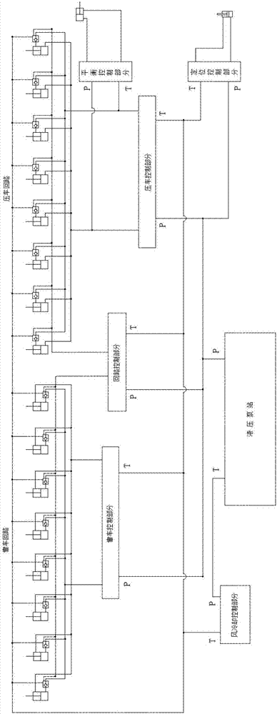
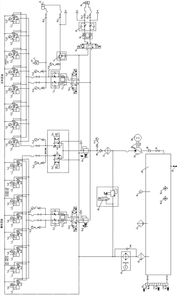
[0023] The dumper hydraulic system shown in the figure also includes a control circuit and a positioning circuit controlled by a hydraulic pump station, wherein the hydraulic pump station uses a single oil pump to supply oil to the main oil circuit, and the main oil circuit is connected to the solenoid valve overflow valve Oil return, the main oil circuit supplies oil to the vehicle circuit oil cylinder group through the pilot pressure reducing valve, electro-hydraulic reversing valve, double hydraulic control check valve, one-way throttle valve and hydraulic control check valve group; The main oil circuit supplies oil to the oil cylinder group of the press circuit through the electro-hydraulic reversing valve, double hydraulic control check valve, one-way throttle valve and hydraulic control check valve group, and the main oil circuit passe...


PUM


Abstract

The invention discloses a dumper hydraulic system comprising a hydraulic power unit, and a parking circuit, a hydraulic circuit, a control circuit and a positioning circuit which are controlled by the hydraulic power unit. The hydraulic power unit is used for supplying oil for a main oil circuit through a single oil pump, and the main oil circuit is connected to an electromagnetic relief valve for oil return; the main oil circuit is used for supplying oil to an oil cylinder of the parking circuit through an electro-hydraulic directional valve, dual hydraulic control check valves, a one-way throttle valve and a hydraulic control check valve; the main oil circuit is used for supplying the oil to the oil cylinder of the hydraulic circuit through the electro-hydraulic directional valve, the dual hydraulic control check valves, the one-way throttle valve and the hydraulic control check valve, and the oil pressure of the main oil circuit is reduced through a pilot-operated reducing valve; the main oil circuit is provided with two branches connected to electromagnetic directional valves separately and then connected to the hydraulic control check valves of the parking circuit and the hydraulic circuit to form the control circuit separately; and the oil pressure of the main oil circuit is adjusted through the electromagnetic directional valves, the dual hydraulic control check valves and the one-way throttle valve, and the main oil circuit is used for supplying the oil to a pin cylinder of the positioning circuit. The system is complete in functions and high in safety.

Description

technical field [0001] The invention relates to the field of dumpers, in particular to a hydraulic system of a dumper. Background technique [0002] The dumper is a professional equipment used for unloading large-scale wagons. It can be used to dump coal, sand and other materials loaded on railway open cars. The dumper is widely used in modern large-scale industrial enterprises such as power plants and mines. Especially in thermal power plants, the dumper is an extremely important production equipment. At present, the dumper mainly uses three coupled vane pumps or two coupled vane pumps to supply oil to different circuits respectively, and a single independent plate or pipe connection valve is selected for the control element, which makes the management of hydraulic system valves complicated and inconvenient. It is inconvenient to install, debug and troubleshoot. In addition, the existing hydraulic system cannot predict whether the press cylinder is relieved, and accidents...

Claims


Application Information

Patent Timeline
Patent Type & Authority Applications(China)
IPC IPC(8): F15B21/08F15B21/04F15B19/00F15B20/00F15B11/16F15B13/06
CPCF15B11/16F15B13/06F15B19/00F15B20/00F15B21/041F15B21/042F15B21/087
Inventor 方明陈新元傅连东湛从昌邓江洪刘永秀姜耀文
Owner WUHAN UNIV OF SCI & TECH
Why Eureka
Try Eureka