Spiral tube type air-air heat exchanger in circular passage

A technology of annular channels and air heat exchangers, applied in the direction of heat exchanger types, indirect heat exchangers, lighting and heating equipment, etc., can solve the problems of poor pressure resistance and thermal expansion adaptability, limited applicable temperature and pressure range, and temperature difference Correction coefficient is small and other problems, to achieve the effect of reducing the flow resistance in the pipe, reducing the total installed weight, and reducing the resistance outside the pipe

Inactive Publication Date: 2017-09-22
XI AN JIAOTONG UNIV
View PDF4 Cites 3 Cited by
  • Summary
  • Abstract
  • Description
  • Claims
  • Application Information

AI Technical Summary

Problems solved by technology

The serpentine tube heat exchanger has a long flow in the tube, a small number of flow channels, high flow resistance in the tube, and the flow arrangement is a downstream heat exchanger, the temperature difference correction coefficient is small, and the heat transfer effect is poor
Compared with coiled tube heat exchangers, plate-fin heat exchangers and original surface heat exchangers are compact in structure, but their pressure resistance and thermal expansion adaptability are poor, their sealing is not good, and their applicable temperature and pressure ranges are limited.

Method used


Image

  • Spiral tube type air-air heat exchanger in circular passage
  • Spiral tube type air-air heat exchanger in circular passage
  • Spiral tube type air-air heat exchanger in circular passage

Examples


Embodiment Construction

[0026] The present invention will be further described in detail below in conjunction with specific embodiments, which are explanations of the present invention rather than limitations.

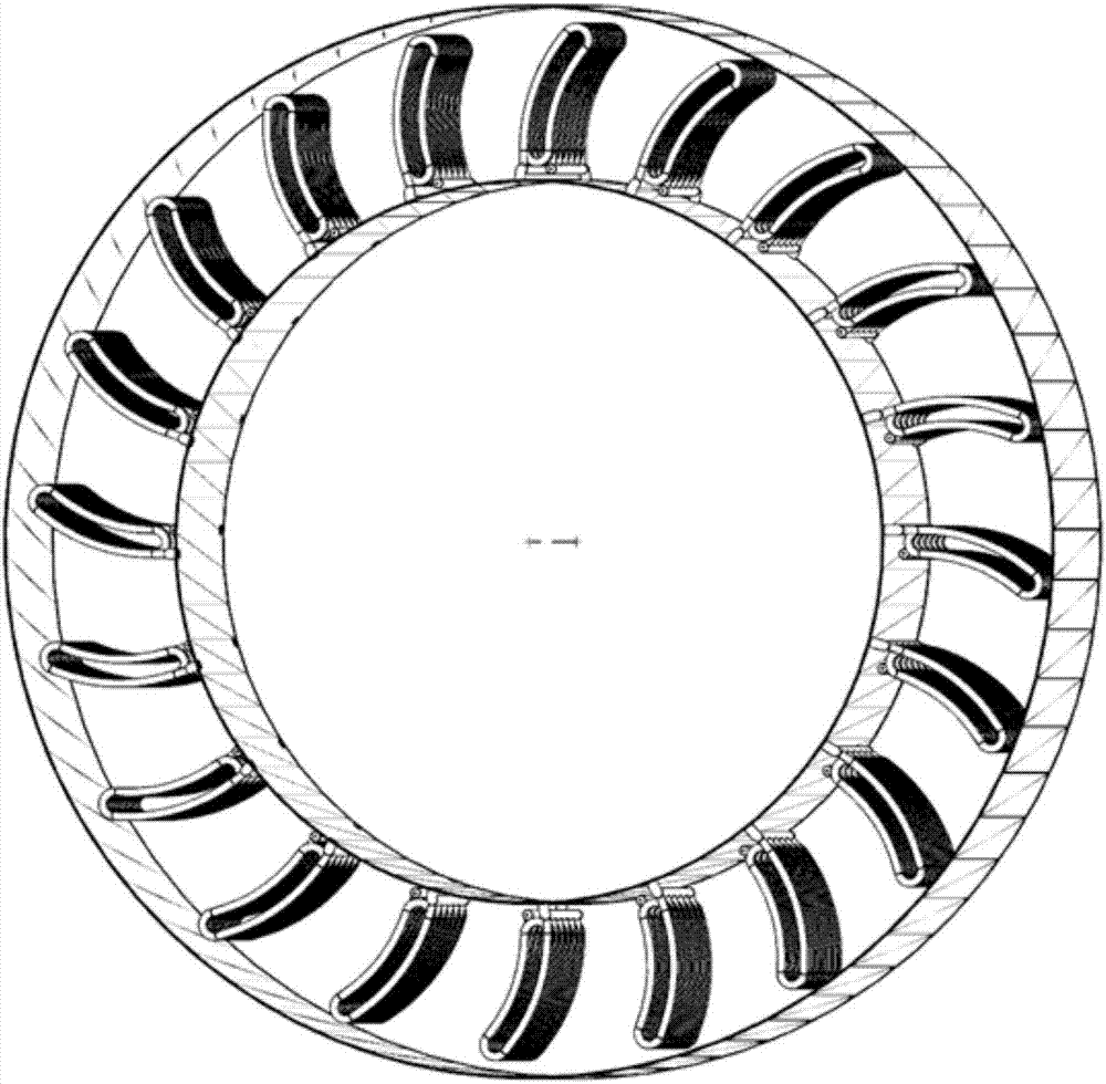
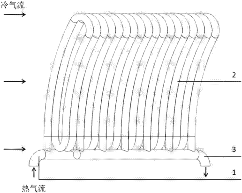
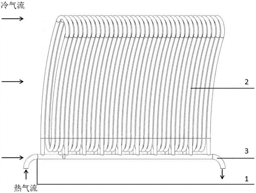
[0027] The present invention is a spiral tube type gas-gas heat exchanger in an annular channel, such as figure 1 and image 3 As shown, it includes a number of heat exchange units uniformly arranged along the circumferential direction of the annular channel; the cold air flow in the annular duct moves axially, and the heat exchange unit includes the hot air flow into the air collection pipe 1 and the hot air flow arranged along the flow direction of the cold air flow. Outflow collector 3, and a number of spiral heat exchange tubes 2 connected with hot air outflow collector 1 and hot air inflow collector 3 at both ends; spiral heat exchange tubes 2 are arranged in sequence along the flow direction of cold airflow to form a heat exchange tube bundle The inlet of the hot air flow into the coll...


PUM


Abstract

The invention discloses a spiral tube type air-air heat exchanger in a circular passage, and relates to the field of air-air heat exchangers. The spiral tube type air-air heat exchanger in the circular passage comprises a plurality of heat exchanging units which are evenly arranged in the circular passage in the circumferential direction of the circular passage. Cold air flow in the circular passage moves in the axial direction. Each heat exchanging unit comprises a hot air flow inlet air collecting pipe and a hot air flow outlet air collecting pipe which are arranged in the flowing direction of the cold air flow and a plurality of spiral heat exchanging pipes, wherein the two ends of each spiral heat exchanging pipe communicate with the hot air flow outlet air collecting pipe and the hot air flow inlet air collecting pipe correspondingly. The spiral heat exchanging pipes are distributed in sequence in the flowing direction of the cold air flow to form a heat exchanging pipe bundle. An outlet of each hot air flow outlet air collecting pipe and an inlet of each hot air flow inlet air collecting pipe are located at the same end of the corresponding heat exchanging unit and penetrate through the inner wall or the outer wall of the circular passage. The other end of each heat exchanging unit is a free end.

Description

technical field [0001] The invention relates to the field of gas-gas heat exchangers, in particular to a spiral tube-type gas-gas heat exchanger in an annular channel. Background technique [0002] Air ducts widely exist in various engineering fields, such as aviation, aerospace, ships, vehicles, nuclear technology, etc. For different fields, air ducts have different forms, and the more common ones are square, circular, and circular. For some complex cutting-edge fields, such as air-space pre-cooling engine external duct, the air flow rate often reaches transonic or supersonic speed. At this time, the heat transfer design and structural design of the heat exchanger must meet the requirements of aerodynamic performance and thermal performance at the same time. Require. Annular air ducts are often found in the external ducts of aero-engines and aerospace pre-cooling engines. At this time, in addition to meeting the flow and resistance characteristics, the heat exchanger must...

Claims


Application Information

Patent Timeline
Patent Type & Authority Applications(China)
IPC IPC(8): F28D7/02
CPCF28D7/024
Inventor 李增耀于广雷于霄沈毅
Owner XI AN JIAOTONG UNIV
Why Eureka
Try Eureka