Fuel gas generator capable of quickly inflating underwater ordnance floating system

A gas generator, fast technology, applied in the direction of weapon accessories, ammunition test, ammunition, etc., can solve the problems affecting the ballistic accuracy, etc., achieve the effect of inflatable speed block, easy installation and sealing, and light weight

Active Publication Date: 2017-09-22
HUBEI INST OF AEROSPACE CHEMOTECH
View PDF6 Cites 6 Cited by
  • Summary
  • Abstract
  • Description
  • Claims
  • Application Information

AI Technical Summary

Problems solved by technology

[0004] In order to solve the problems that the underwater weapon test process needs to be recovered with a rope, which affects the ballistic accuracy, etc., the present invention provides a gas generator tha

Method used


Image

  • Fuel gas generator capable of quickly inflating underwater ordnance floating system
  • Fuel gas generator capable of quickly inflating underwater ordnance floating system
  • Fuel gas generator capable of quickly inflating underwater ordnance floating system

Examples


Embodiment 1

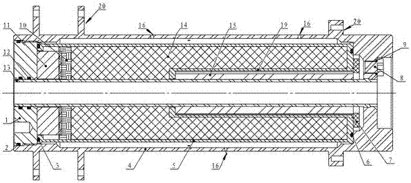
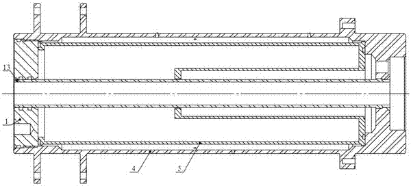
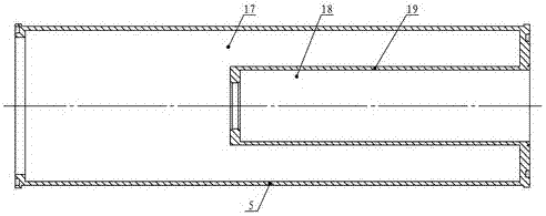
[0033] Refer to attached figure 1, the primer 7 and the seal ring 6 that 5g black powder and potassium boron nitrate are housed are bonded on the base plate of the filter device 5, and the 100g low-temperature gas generating agent drug strip 15 is evenly bonded on the combustion chamber 18 inner walls. Put the bottom plate of the assembled filter device 5 downward into the generator, put 800g of granular low-temperature gas-generating agent particles 14 into the working room, and fill up the remaining space of the working room with a sponge pad 10 . Put the sealing ring 3 into the filter device, and after the sealing rings 2 and 12 are installed in the end cover 1, assemble the end cover 1 with the shell by using the assembly hole of the end cover. Fitting the igniter 8 onto the bottom of the generator completes the generator assembly.

[0034] In a 58L airtight container, an electric current is used to stimulate the ignition test. data such as Figure 5 shown. The maximum...

Embodiment 2

[0036] Refer to attached figure 1 12g igniting drug ring and sealing ring 6 are bonded on the bottom plate of filter device 5, and 80g low-temperature gas generating agent drug strip 15 is evenly bonded on the inner wall of the combustion chamber. Put the bottom plate of the assembled filter device 5 downwards into the generator, put 620g of granular low-temperature gas-generating agent particles 14 into the working room, put the working chamber cavity adjustment pad 11 into the working room, and put the gas-generating drug and the pad into the working room. Sponge pads 10 are used to isolate the blocks. Put the seal ring 3 into the filter device, and after the seal rings 2 and 12 are installed in the end cover 1, use the end cover assembly hole to assemble the end cover and the shell. Fit the igniter onto the bottom of the generator to complete the generator assembly.

[0037] In a 58L airtight container, an electric current is used to stimulate the ignition test. data suc...


PUM


Abstract

The invention discloses a gas generation device capable of providing a gas source for an underwater ordnance floating system. The gas generation device comprises a shell, a combustion chamber and a working chamber which are formed in the shell, and one or more igniters mounted at one end of the shell, wherein a filter sleeve is mounted in the shell; the filter sleeve comprises a large outer sleeve and a small inner sleeve; the combustion chamber is formed through filling the small inner sleeve with a low-temperature gas generant; the working chamber is formed through filling a chamber between the inner wall of the large outer sleeve and the outer wall of the small inner sleeve with the low-temperature gas generant; and a plurality of exhaust holes are formed in the side surface of the shell. The gas generation device has the advantages of simple structure, light weight, low generator inner pressure, stable outlet pressure, low dust, low outlet gas temperature and the like, and requirements of quick floating of underground objects and inflation of airtight sacs in water and air rescue can be met.

Description

technical field [0001] The invention relates to a gas generator. Background technique [0002] The underwater weapon test bomb needs to be recovered during the test to obtain test data. If a long rope is carried into the water during the test, the ballistic performance of the test bomb will be affected. During long-distance horizontal movement, the rope cannot be recovered at all, so a An emergency floating system, the system is composed of a controller, a gas generator, an air bag, etc., and can be installed on the test bomb without affecting the normal operation of the test bomb. When the test bomb is finished, the water depth controller sends an ignition signal to start the gas The generator produces a large amount of low-temperature gas to rapidly expand the capsule to obtain buoyancy, and float the test bomb out of the water. The system requires the gas generator to have the characteristics of large gas output, fast start-up, low gas temperature, and few solid particle...

Claims


Application Information

Patent Timeline
IPC IPC(8): F42B35/00C06B31/04
CPCC06B31/04F42B35/00
Inventor 吴敏杨玲信培培张国涛王小波张新龙余剑
Owner HUBEI INST OF AEROSPACE CHEMOTECH
Why Eureka
Try Eureka