Air source heat pump drying system

An air source heat pump and drying system technology, applied in the field of drying, can solve the problems of unreasonable structure design, poor drying effect, and easy occurrence of moisture return, and achieve the effect of compact structure, modular design and high quality of finished products.

Pending Publication Date: 2017-09-26
刘贵平
View PDF2 Cites 7 Cited by
  • Summary
  • Abstract
  • Description
  • Claims
  • Application Information

AI Technical Summary

Problems solved by technology

[0005] The purpose of the present invention is to overcome the shortcomings of the prior art and provide an air source heat pump drying system to solve the problems of low drying efficiency, large energy consumption, poor drying effect, unreasonable structural design, and problems existing in the existing heat pump drying system. Technical problems prone to moisture return

Method used


Image

  • Air source heat pump drying system
  • Air source heat pump drying system

Examples


Embodiment Construction

[0020] The specific embodiments of the present invention will be further described below in conjunction with the accompanying drawings.

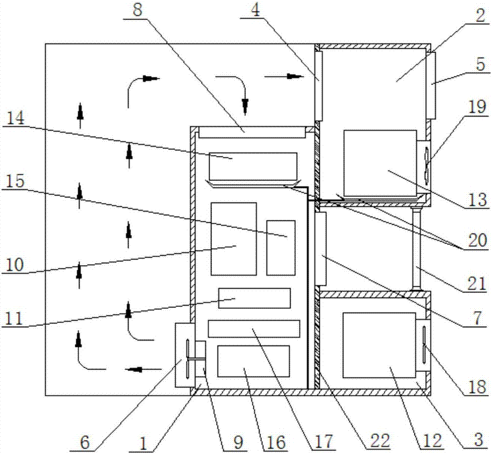
[0021] Such as figure 1 and figure 2 As shown, an air source heat pump drying system includes an indoor cavity 1, an outdoor upper cavity 2 and an outdoor lower cavity 3, the indoor cavity 1, the outdoor upper cavity 2 and the outdoor lower cavity 3 It is arranged as a whole, the indoor cavity 1 is set in the drying room, the outdoor upper cavity 2 and the outdoor lower cavity 3 are both set outside the drying room, and the outdoor upper cavity 2 is set in the outdoor lower cavity 3 above; a connecting support rod 21 is provided between the outdoor upper chamber 2 and the outdoor lower chamber 3;

[0022] One side wall of the outdoor upper chamber 2 is provided with a moisture discharge damper 4 communicating with the drying room, and the upper part of the other side side wall is provided with a heat recovery damper 5 communicated with th...


PUM


Abstract

The invention relates to an air source heat pump drying system, which belongs to the technical field of drying systems. The invention mainly solves the technical problems of low drying efficiency, large energy consumption, poor drying effect, unreasonable structural design and easy occurrence of moisture return existing in the existing heat pump drying system. The technical solution of the present invention is: an air source heat pump drying system, which includes an indoor cavity, an outdoor upper cavity and an outdoor lower cavity, the indoor cavity is set in a drying room, and the outdoor upper cavity The air source heat pump drying system also includes a compressor, a heating condenser, a heat exhausting condenser, a heat-absorbing evaporator, a dehumidifying evaporator, a condensed water collecting tray and a storage liquid tank. The invention has the advantages of compact structure, high drying efficiency, high product quality, wide application range, modular design, compatibility with auxiliary heat sources, simple operation, reasonable structural design, and no influence of ambient temperature and humidity.

Description

technical field [0001] The invention belongs to the technical field of drying, in particular to an air source heat pump drying system. Background technique [0002] Heat pump technology is becoming increasingly mature and widely used in air conditioning, heating, hot water, heat recovery, and drying industries. [0003] The existing heat pump drying system, such as Chinese patent CN201220359802.8 discloses a heat pump drying system for circulating heat recovery, which consists of a drying chamber, a heat pump host system, a return air fan, a cold air fan, a bypass ventilation valve, a return air pipe, and a cold air pipe and hot air duct. The drying chamber is provided with an operation door, an air outlet and an air inlet. The heat pump host system is composed of a condenser, a first refrigerant pipe, a compressor, a second refrigerant pipe, an evaporator, a third refrigerant pipe, an expansion valve, and a fourth refrigerant in order to form a circulation system. The ai...

Claims


Application Information

Patent Timeline
Patent Type & Authority Applications(China)
IPC IPC(8): F26B9/06F26B21/08F26B21/10F25B30/02
CPCF26B9/06F25B30/02F26B21/002F26B21/08F26B21/10
Inventor 刘贵平
Owner 刘贵平
Why Eureka
Try Eureka