Air-tight image chip packaging structure and manufacturing method thereof

A chip packaging structure and airtight technology, which is applied in the fields of electrical components, semiconductor/solid-state device manufacturing, and electric solid-state devices, can solve problems such as low production efficiency, unfavorable image sensor thinning process, and weakened image chip strength.

Inactive Publication Date: 2017-09-29
BEIJING UNIV OF TECH
View PDF7 Cites 5 Cited by
  • Summary
  • Abstract
  • Description
  • Claims
  • Application Information

AI Technical Summary

Problems solved by technology

[0003] The existing traditional high-pixel image sensor chip structure is to lead out the signal by wire bonding, which has high cost and low production efficiency; for the existing wafer-level packaged image chip structure, it is necessary to The TSV (Through Silicon Via) process is used on the non-functional surface, and there are many processes on the image chip, which have high requirements on the support force of the chip, resulting in a relatively large thickness, which is not conducive to the thinning process of the image sensor, and this process is prone to silicon explosion. Case
In addition, the TSV opening also weakens the strength of the image chip, thereby reducing the production yield

Method used


Image

  • Air-tight image chip packaging structure and manufacturing method thereof
  • Air-tight image chip packaging structure and manufacturing method thereof
  • Air-tight image chip packaging structure and manufacturing method thereof

Examples


Embodiment Construction

[0029] In order to make the present invention more obvious and understandable, the specific implementation manners of the present invention will be described in detail below in conjunction with the accompanying drawings. For convenience of description, the components in the structures in the drawings of the embodiments are not scaled according to the normal scale, so they do not represent the actual relative sizes of the structures in the embodiments.

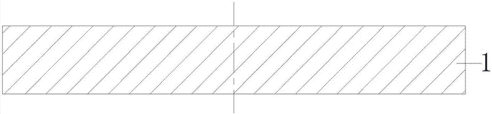
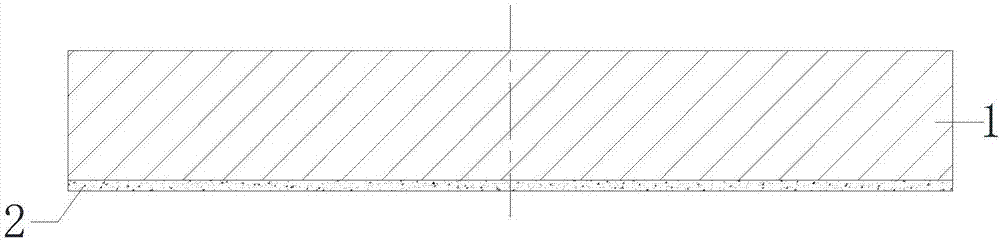
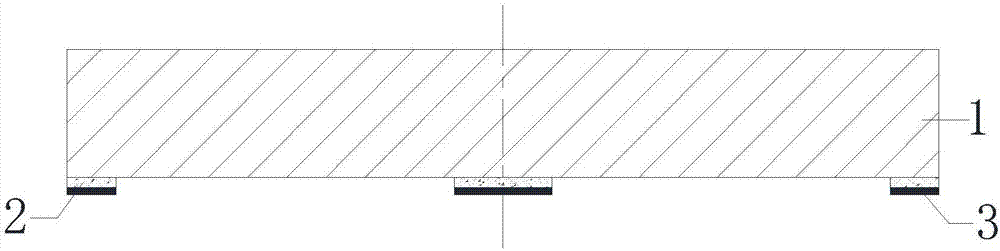
[0030] Such as Figure 14 As shown, the packaging structure of an image chip disclosed in the present invention includes at least one image chip 700 and a cofferdam 4. The image chip 700 includes a functional surface and a non-functional surface opposite to it, and the functional surface includes solder pads 701 and Functional area 702, the front side of the cofferdam 4 includes a conductive circuit 3, the solder pad 701 on the functional surface of the image chip 700 is bonded and electrically connected to the conductive circu...


PUM


Abstract

The invention discloses an air-tight image chip packaging structure and a manufacturing method thereof. A conducting circuit is paved on the front side of a cofferdam, the functional surface of a thinned image chip faces a cavity of the cofferdam, so that a welding pad is attached onto the conducting circuit on the cofferdam for electrical connection, insulating layers are packaged on the side wall of the image chip and the non-functional surface of the image chip, an electric conductor is manufactured inside the insulating layer at the position of the side wall of the image chip, the conducting circuit on the front side of the cofferdam is leaded to the non-functional surface of the image chip, and electrical property is leaded out through a re-routing metal circuit on the non-functional surface insulating layer. According to the packaging technology in the invention, manufacture procedure is not set on the image chip, thinning of an image sensor can be realized, and the packaging reliability is improved. High-cost manufacture procedures such as manufacturing of silicon through holes and deep hole passivation are omitted, and the cost is greatly reduced.

Description

technical field [0001] The invention relates to a semiconductor packaging technology, in particular to an image chip wafer-level packaging technology. Background technique [0002] An image sensor chip is a semiconductor module and a device that converts an optical image into an electronic signal. The electronic signal can be used for further processing or digitization for storage, or for transmitting the image to a display device for display, etc. It is widely used in digital cameras and other electro-optical devices. Image sensor chips are mainly divided into two types: charge-coupled device (CCD) and CMOS image sensor (CIS). Although the CCD image sensor is superior to the CMOS image sensor in terms of image quality and noise, the CMOS sensor can be manufactured with traditional semiconductor production technology, and the production cost is relatively low. At the same time, due to the relatively small number of components used and the short signal transmission distance...

Claims


Application Information

Patent Timeline
Patent Type & Authority Applications(China)
IPC IPC(8): H01L23/31H01L23/488H01L21/50H01L21/56H01L21/60
CPCH01L21/50H01L21/56H01L23/31H01L23/488H01L24/03H01L2224/03
Inventor 秦飞别晓锐唐涛项敏肖智轶
Owner BEIJING UNIV OF TECH
Why Eureka
Try Eureka