
Tri-band filter micro-strip slit antenna

A technology of microstrip slots and antennas, which is applied in the field of triple-frequency filtering microstrip slot antennas, can solve the problems of less research on multi-frequency filtering antennas, and achieve the effects of good filtering characteristics, improved signal-to-noise ratio, and improved selectivity

Pending Publication Date: 2017-09-29
SOUTH CHINA UNIV OF TECH
View PDF5 Cites 6 Cited by
  • Summary
  • Abstract
  • Description
  • Claims
  • Application Information

AI Technical Summary

Problems solved by technology

[0007] In general, the research on filter antennas is changing rapidly nowadays, but there are few studies on multi-frequency filter antennas

Method used


Image

  • Tri-band filter micro-strip slit antenna
  • Tri-band filter micro-strip slit antenna
  • Tri-band filter micro-strip slit antenna

Examples


Embodiment Construction

[0025] The present invention will be further described below in conjunction with specific embodiments.

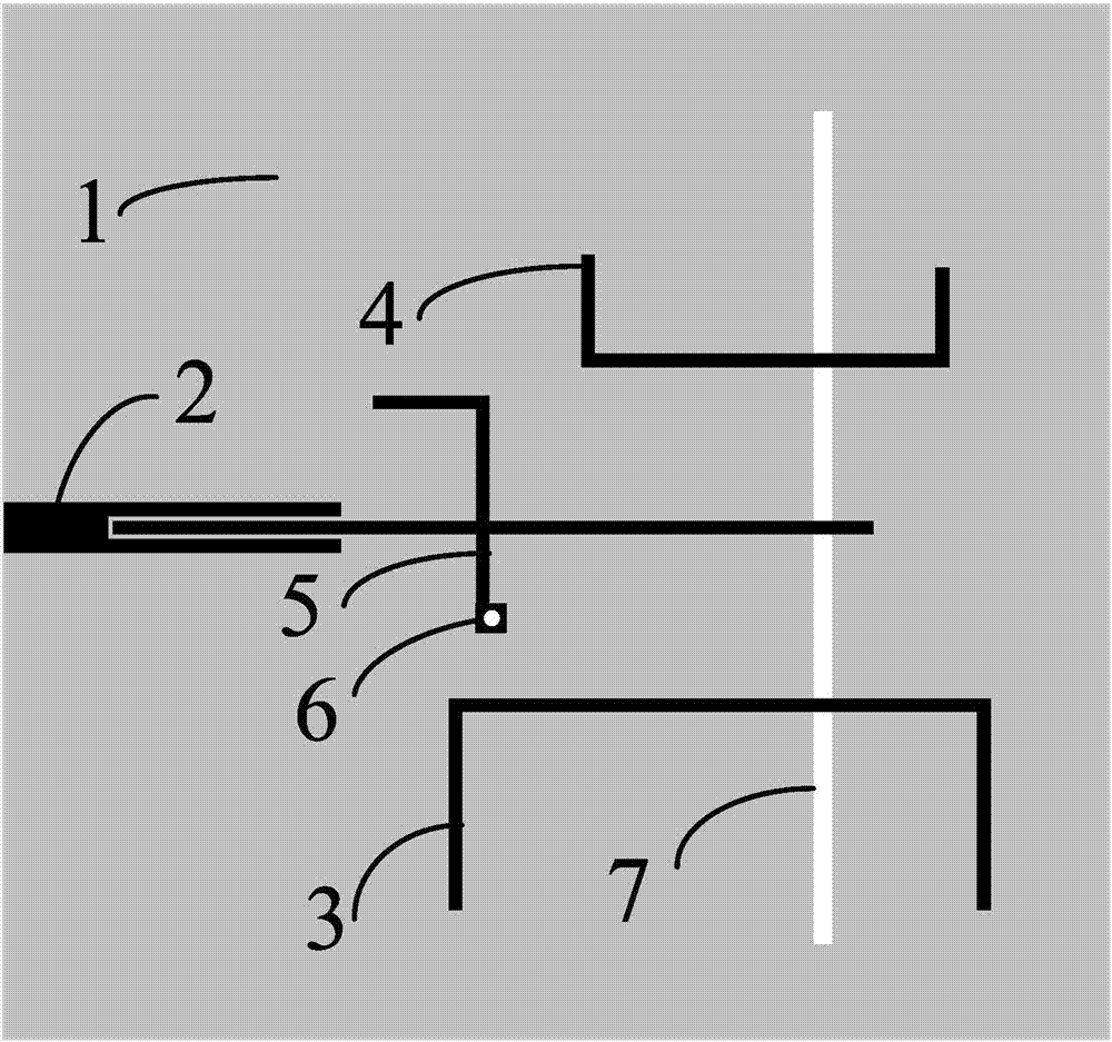
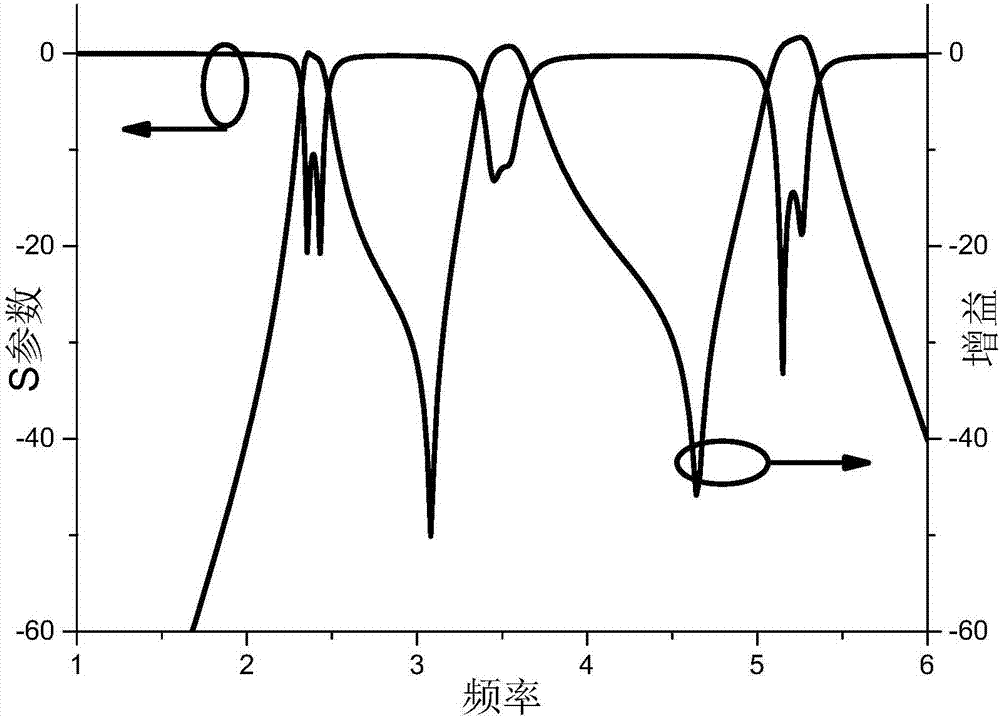
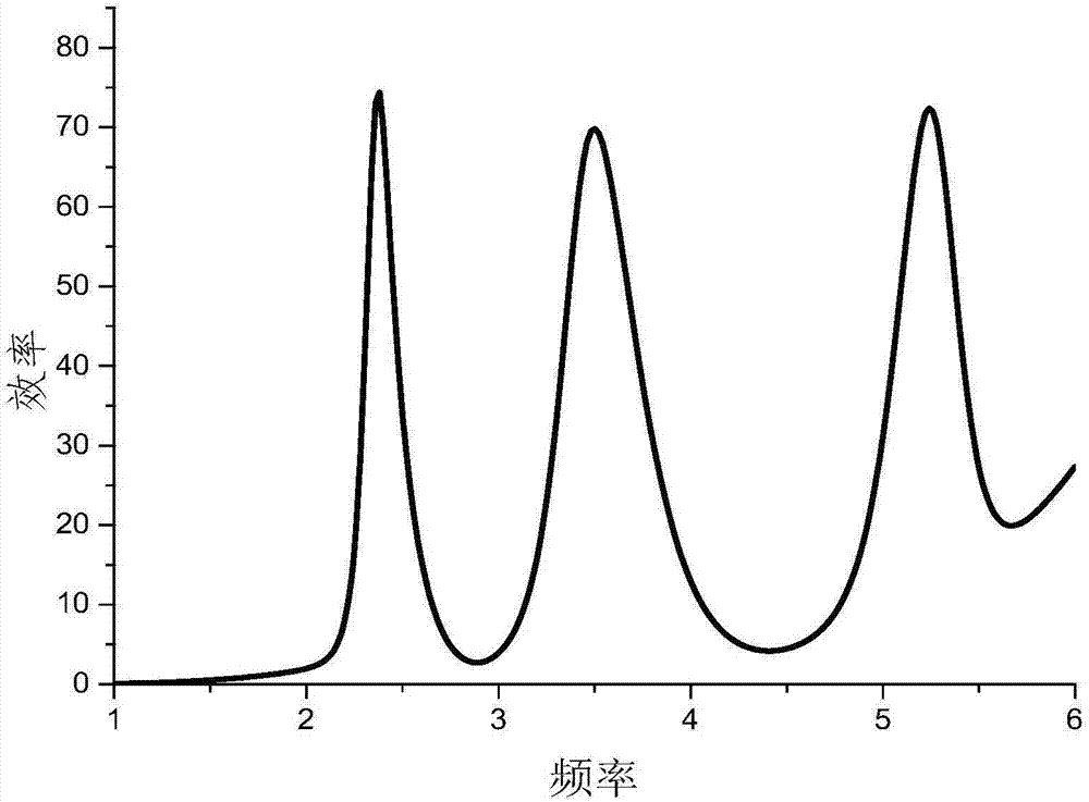
[0026] see figure 1 As shown, the triple-band filter microstrip slot antenna provided in this embodiment includes a dielectric substrate 1 and an input port 2 fabricated on the dielectric substrate 1, a first open-circuit resonator 3 having a half wavelength, and a first open-circuit resonator 3 with two A second open-circuit resonator 4 of one-half wavelength, a cross-shaped resonator 5 and a slotted floor with a rectangular slit 7, wherein the first open-circuit resonator 3 and the second open-circuit resonator 4 are respectively loaded on the slotted floor The rectangular slot 7 on the floor is used to obtain the three-frequency radiation characteristic, the feeder of the input port 2 is loaded on the cross-shaped resonator 5, and then the rectangular slot on the slotted floor is excited by the cross-shaped resonator 5 to obtain the three-frequency filtering effect ; Th...


PUM


Abstract

The invention discloses a tri-band filter micro-strip slit antenna comprising a dielectric substrate, and a group formed on the dielectric substrate and including an input port, a cross-shaped resonator, a first open-circuit resonator with a half wavelength, a second open-circuit resonator with a half wavelength, and a slotted floor with a slit, wherein the first open-circuit resonator and the second open-circuit resonator are loaded on the slit of the slotted floor to obtain tri-band radiation characteristics. The feeder line of the input port is loaded on the cross-shaped resonator. The cross-shaped resonator excites the slit on the slotted floor to obtain a tri-band filtering effect. The tri-band filter micro-strip slit antenna can realize good filtering and radiation characteristics, and has flexible design, a low profile, low cost and high selectivity.

Description

technical field [0001] The present invention relates to the technical field of antennas, in particular to a three-frequency filtering microstrip slot antenna. Background technique [0002] With the rapid development of wireless communication in recent years, filter antennas have attracted widespread attention due to their integrated design of filters and antennas. By using the antenna as the last-order resonator of the filter, the gain of the filter antenna will also be selective while obtaining the reflection coefficient with the filter response. Compared with the traditional filter antenna cascaded design through the transmission line, this filter antenna structure avoids the impedance mismatch problem in the traditional design and reduces the overall size of the system. [0003] Most of the current research on filter antennas is based on single-frequency antennas, while dual-frequency filter antennas are rare, and tri-frequency and above are basically in a blank stage. ...

Claims


Application Information

Patent Timeline
IPC IPC(8): H01Q1/38H01Q1/50H01Q5/10H01Q5/28H01Q5/321H01Q13/10
CPCH01Q1/38H01Q1/50H01Q5/10H01Q5/28H01Q5/321H01Q13/106
Inventor 钱建锋陈付昌
Owner SOUTH CHINA UNIV OF TECH
Learn More