Al technical title is built by PatSnap Al team. It summarizes the technical point description of the patent document.
A technology of clamping device and pneumatic device, which is applied in the directions of engraving, processing models, decorative art, etc., can solve the problems of inflexible installation, low production efficiency, and damage to the surface of the workpiece, so as to ensure health, reduce labor intensity, increase The effect of high clamping force
Active Publication Date: 2017-10-03
HEFEI SIWEI CNC MACHINERY
View PDF7 Cites 10 Cited by
Summary
Abstract
Description
Claims
Application Information
AI Technical Summary
This helps you quickly interpret patents by identifying the three key elements:
Problems solved by technology
Method used
Benefits of technology
Problems solved by technology
The engraving machine is one of the core equipment for the rapid development of modern industry, and it is widely used. The existing engraving machine is generally equipped with a zigzag working surface on the workbench, so as to prevent the workpiece from slipping and avoid engraving deviation, which may cause Defective products, but the clamping device of the prior art is obviously defective, which is easy to cause damage to the surface of the processed workpiece, or even deformation, and the processed surface is generally difficult to repair after wear, the contact area is small, the friction is small, it is easy to slide, and it is not stable. The force of the existing clamping device after clamping is difficult to adjust, without further increasing the clamping force, it cannot be installed flexibly, resulting in greatly reduced machining accuracy and assembly accuracy
In addition, the existing clamping devices are generally fixed on the workbench, and the position cannot be flexibly adjusted according to the size and thickness of the plate, and continuous position adjustment cannot be realized. When clamping the plate, the staff generally needs to place the plate on the work surface Carry out clamping installation, after the processing is completed, another plate is taken for clamping installation, and the cycle repeats, the labor intensity of the staff is very high, and the production efficiency is also very low. Low, unable to adapt to the height of the staff to work, if things go on like this, the staff will have lumbar muscle strain, which will damage the health of the staff
Method used
Image
Click on the blue label to locate the original text in one second.
Reading with bidirectional positioning of images and text.
Examples
Embodiment Construction
[0018] In order to make the object, technical solution and advantages of the present invention clearer, the present invention will be further described in detail below in conjunction with the accompanying drawings and embodiments. It should be understood that the specific embodiments described here are only used to explain the present invention, not to limit the present invention.
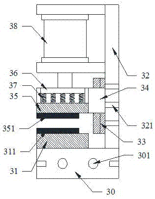
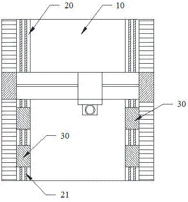
[0019] like figure 1 As shown, the present invention provides a schematic structural view of a clamping device for engraving, such as figure 2 As shown, the top view of the clamping device of the present invention located on the workbench includes a support base 30, the support base 30 is installed on the workbench 10, the support base 30 is provided with a guide hole 301, and the upper end of the support base 30 is provided with a fixed bottom plate 31 and the vertical plate 32, the vertical plate 32 is connected with an adjustment slide plate 33, and the adjustment slide plate 33 is slidably co...
PUM
Abstract
The invention discloses clamping devices used for carving machining. The clamping devices each comprise a supporting seat. The supporting seats are mounted on a worktable. Fixed bottom plates and vertical plates are arranged on the upper end faces of the supporting seats. Adjusting sliding plates are connected with the vertical plates and slidably connected with movable caliper bodies. The movable caliper bodies are fixedly connected with adjusting pressing plates. Pushing plates are arranged above the adjusting pressing plates. Elastic elements are arranged between the adjusting pressing plates and the pushing plates. Pneumatic devices are fixedly mounted on the upper portions of the vertical plates and fixedly connected with the pushing plates. Electromagnets and gasket sucking discs are arranged on the fixed bottom plates and the adjusting pressing plates correspondingly. According to the clamping devices used for carving machining, by arranging the pneumatic devices, workpieces can be automatically clamped, the clamping force is large, and the labor intensity is large. By arranging the electromagnets and gasket sucking discs, the situation that the workpieces do not slide is guaranteed, the clamping force is further increased, and fixity is better. The elastic elements are arranged between the fixed bottom plates and the adjusting pressing plates, so that adjusting of the clamping force is facilitated, and damage to the workpieces is avoided.
Description
technical field [0001] The invention relates to the technical field of engraving machines, in particular to a clamping device for engraving. Background technique [0002] Engraving machine is a commonly used engraving equipment, used to engrave various sculptures and models. With people's understanding and mastery of engraving machines, the application scope and application level will gradually increase, such as advertising industry, seal industry, craft gift industry, art model industry, wood processing industry, mold industry and so on. Machinable materials include acrylic, two-color board, PVC, ABS board, stone, imitation stone, metal, aluminum-plastic board and other materials. The application of engraving machines in the advertising industry is mainly: engraving and cutting various types of signs, coordinate signs, marble, copper, fonts, fonts, various signs, trademarks and other metal materials. The engraving machine is one of the core equipment for the rapid develop...
Claims
Application Information
Patent Timeline
Application Date:The date an application was filed.
Publication Date:The date a patent or application was officially published.
First Publication Date:The earliest publication date of a patent with the same application number.
Issue Date:Publication date of the patent grant document.
PCT Entry Date:The Entry date of PCT National Phase.
Estimated Expiry Date:The statutory expiry date of a patent right according to the Patent Law, and it is the longest term of protection that the patent right can achieve without the termination of the patent right due to other reasons(Term extension factor has been taken into account ).
Invalid Date:Actual expiry date is based on effective date or publication date of legal transaction data of invalid patent.