Vehicle separation determining and traffic flow surveying device and corresponding determining and surveying method

A traffic flow and vehicle separation technology, which is applied in the field of judgment investigation, vehicle separation judgment, and traffic flow investigation equipment, can solve the problems of high cost and high error rate, and achieve the effect of low requirements, high compatibility and long service life

Active Publication Date: 2017-10-03
郑州睿之鲲机电科技股份有限公司
View PDF8 Cites 0 Cited by
  • Summary
  • Abstract
  • Description
  • Claims
  • Application Information

AI Technical Summary

Problems solved by technology

[0005] The purpose of the present invention is to solve the problem of high error rate or high cost in the way of traffic flow detection in the prior art

Method used


Image

  • Vehicle separation determining and traffic flow surveying device and corresponding determining and surveying method
  • Vehicle separation determining and traffic flow surveying device and corresponding determining and surveying method
  • Vehicle separation determining and traffic flow surveying device and corresponding determining and surveying method

Examples


Embodiment 1

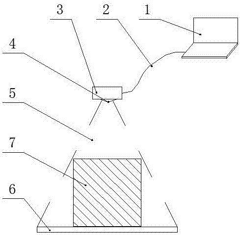
[0041] Embodiment 1: a kind of traffic flow monitoring system, see figure 1 , including a barcode area corresponding to the width of the road, and a video recording and detection device above the bar code area that covers the road width. A single-chip microcomputer connected by component communication; the barcode area includes a certain number of strips 8 with a width of a and a spacing of 2a to 5a. The barcode area forms a zebra crossing with an inclination angle β to the road direction, and the inclination angle β is between 20° and 90°. a is less than 6cm.

[0042] There is an installation angle α between the camera and the road direction, and the installation angle α is consistent with the inclination angle β.

[0043] The camera detection device is installed above the middle of the road, at a height of 4.5-5 meters from the ground. Easy access for most vehicles.

[0044] An optical lens 4 for masking is installed outside the lens of the video camera. The strip length...

Embodiment 2

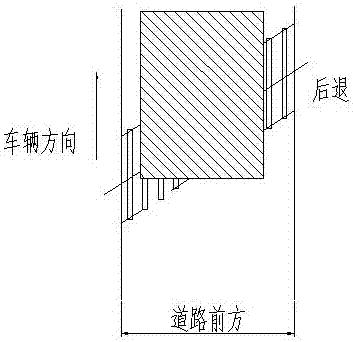
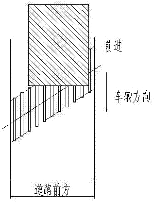
[0057] Embodiment 2: working principle is the same as embodiment 1, as Figures 8 to 13 , the difference is that the installation methods are different. In this embodiment, a camera column and a barcode column are respectively installed at both ends of the road. detection device. When the vehicle passes by, the barcode is blocked in the vertical direction, and the recording device records the information and feeds back the signal to the single-chip microcomputer, and further transmits the relevant data to the upper computer components. At the same time, different from the simultaneous measurement of the vehicle width in Embodiment 1, the present embodiment can simultaneously measure the vehicle height.

[0058] At the same time, there is a supplementary light device, which does not affect the use when there is a lack of external light sources.


PUM


Abstract

The invention relates to a vehicle separation determining and traffic flow surveying device and a corresponding determining and surveying method, and aims at solving the problems of high error rate and low recognizing speed of a vehicle traffic flow detection mode in the prior art. The device comprises a bar code area corresponding to road width, and a shooting and video recording detecting device which is arranged above the bar code area and covers the road width with the shooting range, wherein the shooting and video recording detecting device comprises a camera, a CCD linear sensor for receiving a light source of the camera and transmitting to a photoelectric conversion element, and a single-chip microcomputer which is in communication connection with the photoelectric conversion element; the bar code area comprises a certain quantity of stripy belts of which the width is a and the intervals range from 2a to 5a; and the bar code area forms zero stripes which are inclined by angle beta relative to the road direction. The device has the beneficial effects that the real-time drive-in and drive-out conditions of vehicles can be quickly analyzed through the special shooting and video recording detecting device and according to the shape of bar codes, and the data of forward moving or backward moving of the vehicle after stopping in a short time beside the detecting device can be determined; and a pavement is prevented from being damaged during the mounting process.

Description

technical field [0001] The invention relates to the field of highway toll stations and traffic flow investigation devices, in particular to a vehicle separation judgment, traffic flow investigation equipment and a corresponding judgment and investigation method. Background technique [0002] Vehicle separation is the supporting technology of highway toll system and traffic flow investigation system. The road toll collection system is composed of lane toll collection units connected in parallel. The equipment of the lane toll collection unit controls the toll collection process. Quotation device, toll ticket printer, toll release electric railing, vehicle separation detection system, these devices rely on a stable vehicle separation system. Traffic flow survey refers to the number of vehicles passing on a lane within a certain period of time. It is an important indicator to measure the degree of road congestion in a city, and it is also one of the main reference standards fo...

Claims


Application Information

Patent Timeline
Patent Type & Authority Applications(China)
IPC IPC(8): G08G1/04G08G1/056G08G1/065
CPCG08G1/04G08G1/056G08G1/065Y02T10/40
Inventor 冯旭明安建郑
Owner 郑州睿之鲲机电科技股份有限公司
Why Eureka
Try Eureka