Low switching frequency operation control method for new-type high power asynchronous motor

An asynchronous motor, low switching frequency technology, used in motor control, motor generator control, electronic commutation motor control, etc., can solve problems such as poor dynamic performance, reduce switching frequency, high current harmonics, etc., to improve reliability. and high efficiency, the effect of reducing the switching frequency

Active Publication Date: 2017-10-03
GUANGXI UNIV
View PDF3 Cites 5 Cited by
  • Summary
  • Abstract
  • Description
  • Claims
  • Application Information

AI Technical Summary

Problems solved by technology

[0003] Usually, the conventional PWM control motor system will bring large current harmonics when the switching frequency is reduced, resulting in large copper consumption and torque ripple, which seriously affects the safety and efficiency of mechanical equipment. Optimum pulse Wide modulation needs to be calculated offline, and the dynamic performance is poor. However, predictive control has a unique and effective solution to this problem. Generally, the boundary circle is often used as

Method used


Image

  • Low switching frequency operation control method for new-type high power asynchronous motor
  • Low switching frequency operation control method for new-type high power asynchronous motor
  • Low switching frequency operation control method for new-type high power asynchronous motor

Examples


Embodiment Construction

[0035] The specific embodiment of the present invention will be further described below in conjunction with accompanying drawing:

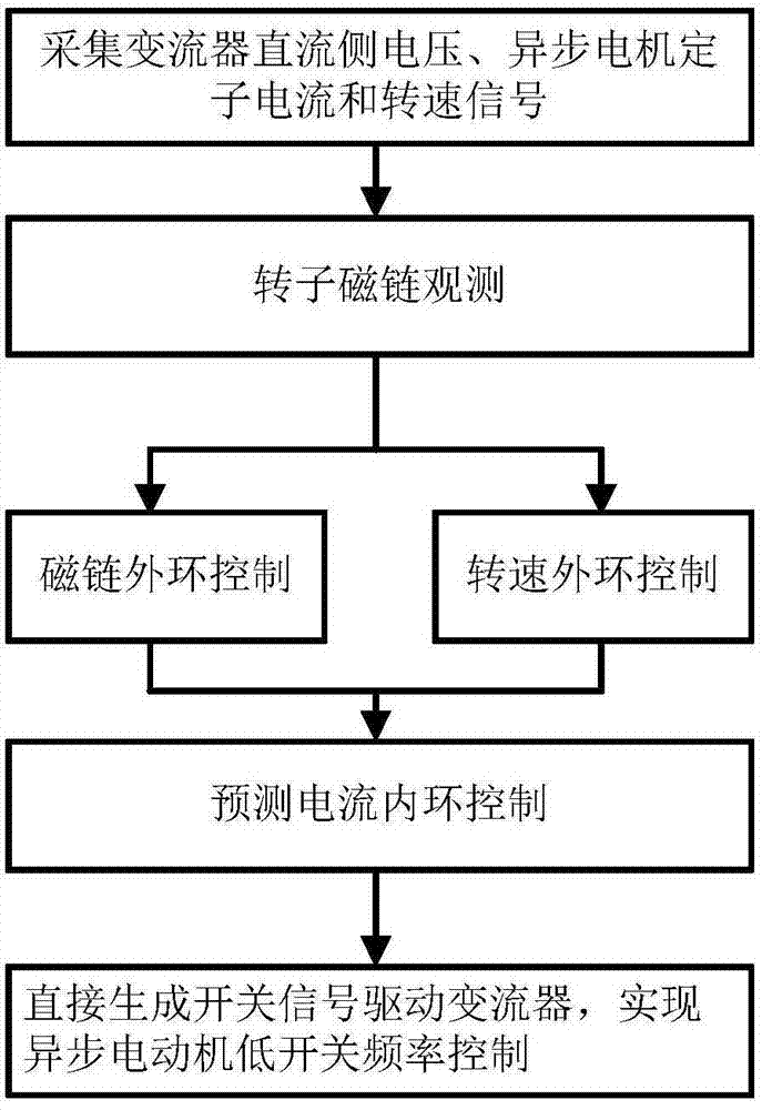
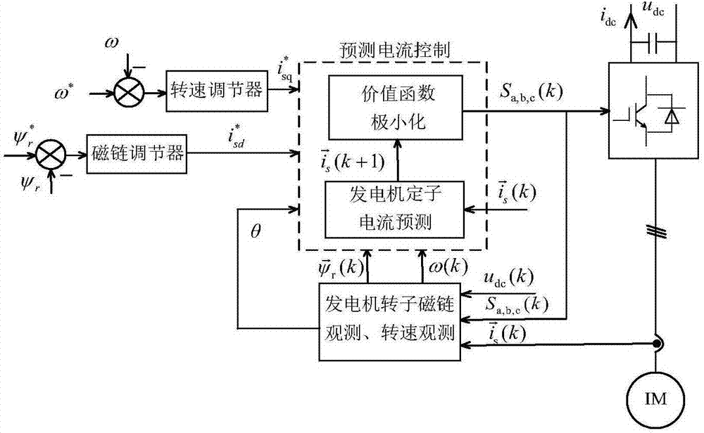
[0036] Such as figure 1 , figure 2 As shown, a new type of high-power asynchronous motor low switching frequency operation control method is characterized in that it includes the following steps:

[0037] S1), signal acquisition: real-time acquisition t k The DC side voltage u of the time converter dc (k), asynchronous motor stator current Asynchronous motor speed ω(k);

[0038] S2), rotor flux observation: at t k moment, using the switching signal S a,b,c (k) and DC side voltage u dc (k) Synthetic motor stator voltage vector Its calculation formula is:

[0039]

[0040] In the stationary coordinate system, the rotor flux vector of the asynchronous motor is:

[0041]

[0042] And according to the obtained rotor flux vector Get the rotor flux vector amplitude ψ r (k), the specific calculation expression is:

[0043]

[004...


PUM


Abstract

The invention discloses a low switching frequency operation control method for a new-type high power asynchronous motor. The method comprises the steps of signal collection, flux linkage observation, flux linkage outer ring control and rotation speed outer ring control, and prediction current inner ring control. An inverter direct current side voltage and a motor stator current are obtained through utilization of collection signals; rotor flux linkage is obtained through calculation; flux linkage closed loop is realized to obtain a d-axis current reference value; the rotation speed of an asynchronous motor is obtained through utilization of the collection signals; rotation speed closed loop is realized to obtain a q-axis current reference value; and a switching signal is directly generated through the prediction current inner ring control, thereby realizing the control of the inverter over the motor. According to the method, a boundary is appointed to be an oval with a long d-axis and a short q-axis in a dq synchronous coordinate system, so the switching frequency operation control with a relatively low linear modulation mode is realized; the switching frequency is reduced by releasing relatively high errors to a d-axis; moreover, the problem of increasing an additional harmonic current is avoided through utilization of the feature that a motor rotor time constant is relatively high; and the motor system operation reliability and high efficiency under the low switching frequency are improved.

Description

technical field [0001] The invention relates to the technical field of motors, in particular to a novel high-power asynchronous motor low switching frequency operation control method. Background technique [0002] The component with the highest failure probability in the motor system is the converter. The failure rate of the motor system caused by the converter is over 57%. However, if the switching frequency is too high, it will generate a large switching loss, which will not only shorten the life of the switching device but also It will reduce the output power of the high-power asynchronous motor system. Therefore, in the field of high-voltage high-power motor systems such as high-speed rail, aviation, offshore wind power, etc., in order to improve the reliability and efficiency of system operation, the switching frequency is generally required to be no higher than 1kHz. [0003] Usually, the conventional PWM control motor system will bring large current harmonics when th...

Claims


Application Information

Patent Timeline
IPC IPC(8): H02P21/00
CPCH02P21/00H02P2207/01
Inventor 卢子广叶伟清洪鹤隽林靖宇朱沙邵磊
Owner GUANGXI UNIV
Why Eureka
Try Eureka