Floating type surface finishing system executer

A floating and actuator technology, applied in the field of machining, can solve the problems of complex structure and difficult to ensure the air tightness of the structure, and achieve the effect of improving flexibility and avoiding damage.

Pending Publication Date: 2017-10-10
南通理工智能制造技术有限公司 +2
View PDF8 Cites 2 Cited by
  • Summary
  • Abstract
  • Description
  • Claims
  • Application Information

AI Technical Summary

Problems solved by technology

At present, most floating surface finishing actuators use pneumatic, hydraulic, magnetic and other d

Method used


Image

  • Floating type surface finishing system executer
  • Floating type surface finishing system executer
  • Floating type surface finishing system executer

Examples


Embodiment Construction

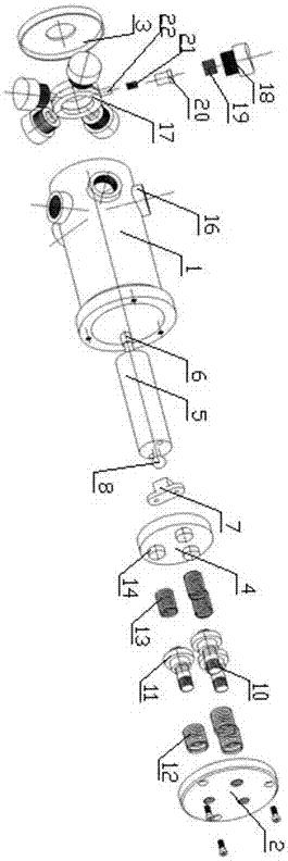
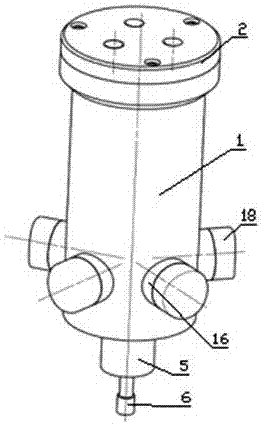
[0019] Such as Figure 1-4 As shown, the present invention comprises a cylindrical shell 1 with openings at both ends, an end cover 2 is connected to the upper end of the cylindrical shell 1, a rubber dustproof cover 3 is connected to the lower end, and a sliding fit is arranged in the cylindrical shell 1. Buffer gland 4.

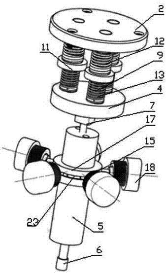
[0020] A high-speed shaft 5 is arranged in the cylindrical shell 1 below the buffer gland 4, a ball seat 7 is installed in the middle of the lower end surface of the buffer gland 4, and a ball head fitted in the ball seat 7 is connected to the upper end of the high-speed shaft 5 8. The lower end of the high-speed shaft 5 passes through the dust cover 3 downwards and is connected with the cutter head holder 6 .

[0021] The upper cavity of the buffer gland 4 is provided with an axial floating mechanism 9. The axial floating mechanism 9 includes three screw rods 10 uniformly distributed in the cavity below the buffer gland 4. The lower ends of the screw rods...


PUM


Abstract

The invention discloses a floating type surface finishing system executer, and belongs to the technical field of machining. The floating type surface finishing system executer comprises a cylindrical shell with the two ends opened. The upper end of the cylindrical shell is connected with an end cover, and the lower end of the cylindrical shell is connected with a dustproof cover. A buffering gland is arranged in the cylindrical shell in a sliding fit manner. The part, below the buffering gland, of the cylindrical shell is internally provided with a high-speed shaft. The lower end of the high-speed shaft downwards penetrates the dustproof cover and is connected with a tool bit clamp. A radial floating mechanism is arranged between the high-speed shaft and the cylindrical shell. A cavity above the buffering gland is internally provided with an axial floating mechanism. In the work process of the floating type surface finishing system executer, axial force exerted on the executer is transmitted into the inner axial floating mechanism, radial force is transmitted to the radial floating mechanism, a tool can conduct following machining on component burrs, and tool and component damage caused by component and positioning errors can be effectively avoided; and the work efficiency of workpiece surface polishing, mechanical deburring and the like and the surface quality are greatly improved.

Description

technical field [0001] The invention belongs to the technical field of mechanical processing, and in particular relates to a floating surface finishing system actuator arranged at the end of a manipulator. Background technique [0002] In the field of traditional machinery manufacturing, the surface finish of the workpiece is manually operated. This method is time-consuming and laborious, and the production efficiency is low, and the quality of the parts is unstable. Using industrial robots instead of manual deburring operations can effectively improve production efficiency, reduce costs, and ensure that parts are deburred. However, due to the positioning error of the robot, it is easy to break the tool or the parts are accidentally damaged when using a rigid tool for deburring. The floating deburring actuator can effectively solve this problem. It can make the tool follow the burrs of the parts, and can effectively avoid damage to the tool and parts caused by parts and posi...

Claims


Application Information

Patent Timeline
IPC IPC(8): B23D79/00B23P9/00
CPCB23D79/00B23P9/00
Inventor 裴宏杰刘成石王贵成李朱锋
Owner 南通理工智能制造技术有限公司
Why Eureka
Try Eureka