Cutting device for bamboo product processing
A technology for cutting devices and bamboo products, which is applied in the direction of manufacturing tools, wood processing equipment, plant material machining, etc. It can solve the problems of cumbersome operation, potential safety hazards, and low feeding efficiency, so as to improve cutting accuracy, shorten strokes, and improve processing. efficiency effect
- Summary
- Abstract
- Description
- Claims
- Application Information
AI Technical Summary
Problems solved by technology
Method used
Image

Examples
Embodiment Construction
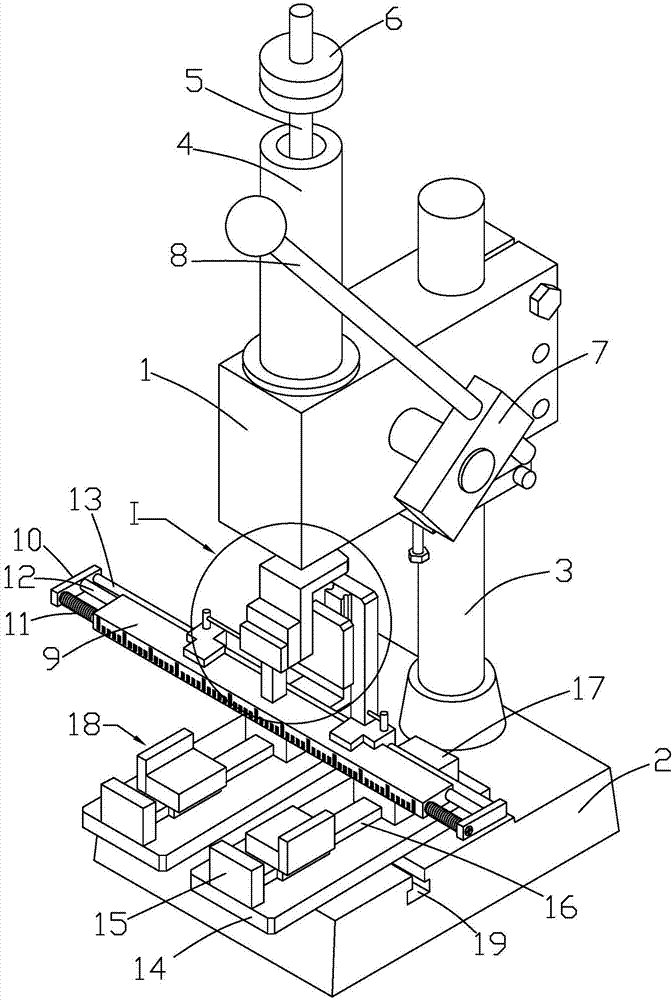
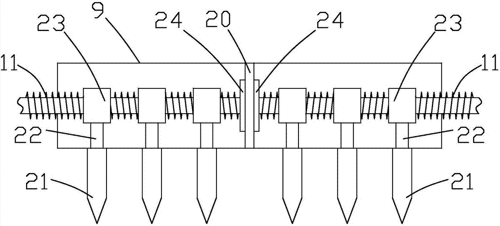
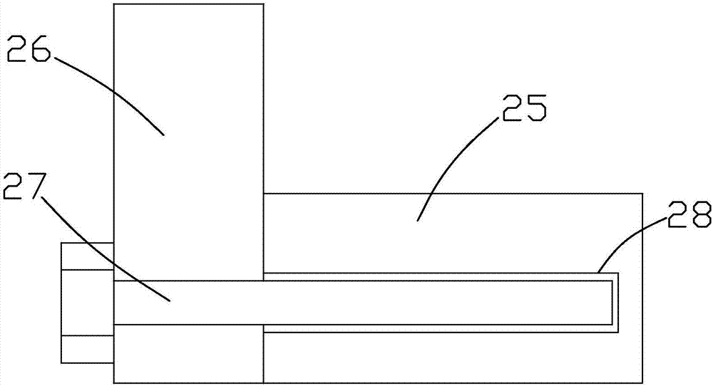
[0027] Such as Figure 1 to Figure 4 As shown, it is a cutting device for bamboo product processing according to the present invention, comprising a cantilever 1, a base plate 2, an extruding mechanism, a cutting mechanism and a feeding mechanism, the cantilever 1 is fixedly connected above the base plate 2 through a vertical rod 3, and the extruding mechanism is located at On the cantilever 1, the extruding mechanism includes a positioning sleeve 4, an extruding rod 5, a rotating block 7 and a handle 8. The positioning sleeve 4 is fixedly connected to the top surface of the cantilever 1, and the extruding rod 5 is movably connected to the positioning sleeve 4. Inside, and through the positioning sleeve 4, the top end of the extrusion rod 5 is fixedly connected with the positioning plate 6, and the bottom end of the extrusion rod 5 is connected to the limit mechanism. When the handle 8 is turned, the external force acts on the extrusion rod 5 , so that the extrusion rod 5 driv...
PUM
 Abstract
Description
Claims
Application Information
 - R&D
- Intellectual Property
- Life Sciences
- Materials
- Tech Scout
- Unparalleled Data Quality
- Higher Quality Content
- 60% Fewer Hallucinations
Browse by: Latest US Patents, China's latest patents, Technical Efficacy Thesaurus, Application Domain, Technology Topic, Popular Technical Reports.
© 2025 PatSnap. All rights reserved.Legal|Privacy policy|Modern Slavery Act Transparency Statement|Sitemap|About US| Contact US: help@patsnap.com