

Hydro-electric hybrid energy saving system for lifting mechanism
A lifting mechanism and energy-saving system technology, applied in the direction of current collectors, lifting devices, electric vehicles, etc., can solve problems such as low efficiency, and achieve the effects of avoiding throttling loss, reducing installed power, and stable output
- Summary
- Abstract
- Description
- Claims
- Application Information
AI Technical Summary
Problems solved by technology
Method used
Image

Examples
Embodiment 1
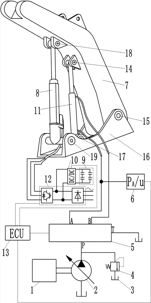
[0027] Such as figure 2 As shown, a hydraulic-electric hybrid energy-saving system for a lifting mechanism includes a power source 1, a hydraulic pump 2, a fuel tank 3, an overflow valve 4, a hydraulic circuit 5, two boom hydraulic cylinders 11, a boom 7, A control unit 13, an electric cylinder 8, a motor speed controller 12, a bidirectional DC / DC converter 10, a supercapacitor group 9, a pressure sensor 6, the output shaft of the power source is connected to the hydraulic pump, and the oil outlet of the hydraulic pump is connected to the hydraulic circuit. The oil inlet P is connected to the oil inlet of the relief valve, and the oil outlet of the relief valve is connected to the fuel tank; the oil return port T of the hydraulic circuit is connected to the fuel tank; The pipeline is connected to the working oil port A and the working oil port B of the hydraulic circuit, and the pressure sensor is installed on the pipeline connected to the rodless chamber of the boom hydrauli...
Embodiment 2
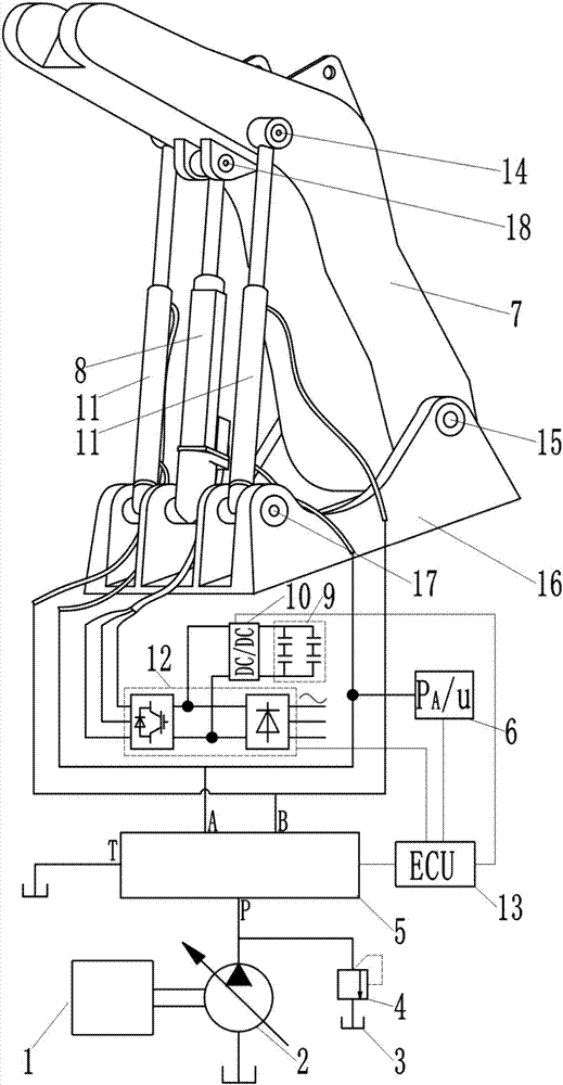
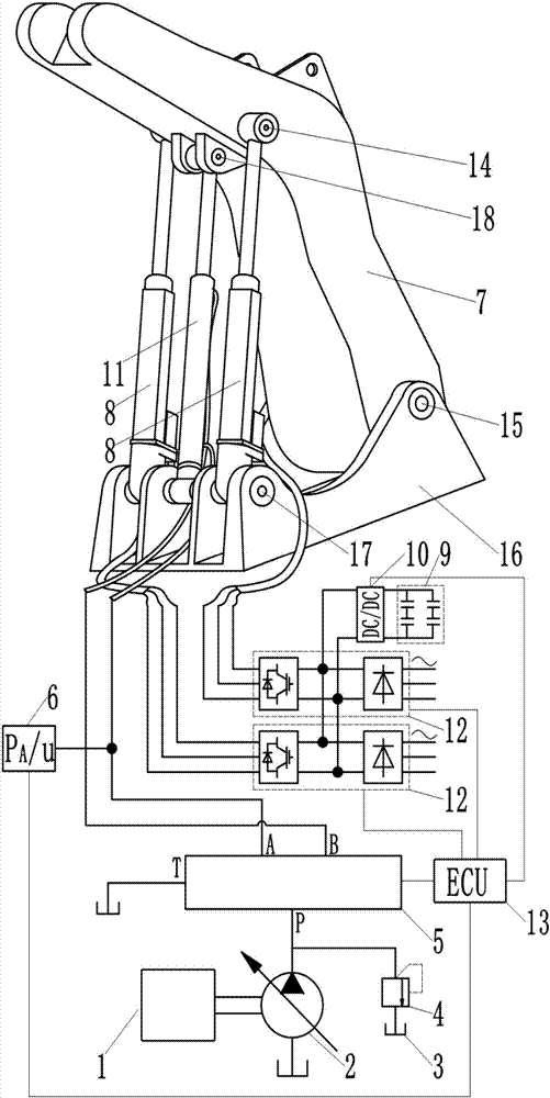
[0030] Such as image 3 As shown, a hydraulic-electric hybrid energy-saving system for a lifting mechanism includes a power source 1, a hydraulic pump 2, a fuel tank 3, an overflow valve 4, a hydraulic circuit 5, a boom hydraulic cylinder 11, a boom 7, a control Unit 13, two electric cylinders 8, two motor speed controllers 12, bidirectional DC / DC converter 10, supercapacitor group 9, pressure sensor 6 power source output shaft is connected to the hydraulic pump, and the oil outlet of the hydraulic pump is connected to the hydraulic pressure The oil inlet P of the circuit is connected to the oil inlet of the relief valve, and the oil outlet of the relief valve is connected to the oil tank; the oil return port T of the hydraulic circuit is connected to the oil tank; the rodless cavity and the rod cavity of the boom hydraulic cylinder are respectively The pipeline is connected to the working oil port A and the working oil port B of the hydraulic circuit, and the pressure sensor is...
Embodiment 1 and Embodiment 2
[0032] Embodiment 1 and embodiment 2 all adopt following control method:
[0033] When the lifting mechanism starts to work, the control unit controls the working state of the motor speed controller and the bidirectional DC / DC converter according to the comparison result of the output signal u of the pressure sensor and its preset value: when the boom is lowered, the output signal of the pressure sensor When u is lower than its preset value, the driving motor of the electric cylinder is in the power generation state at this time, and the control unit controls the motor speed controller and the bidirectional DC / DC converter to work, so that the electric energy generated by the driving motor of the electric cylinder is converted by bidirectional DC / DC In this way, the gravitational potential energy of the boom is directly converted into electric energy and partially recovered; when the boom is raised, the output signal u of the pressure sensor is higher than its preset value, and...
PUM
 Abstract
Description
Claims
Application Information