Pipe pile with post-pressure-grouting grouting pipes and construction method of pipe pile

A construction method and technology of grouting pipes, which are applied in sheet pile walls, foundation structure engineering, construction, etc., can solve the problems of only entering into strong weathered mudstone layers, long engineering piles, and small compression modulus, etc., to achieve Effects of reducing settlement, reducing pile length, and increasing compressive modulus

Active Publication Date: 2017-10-10
MCC TIANGONG GROUP
View PDF5 Cites 7 Cited by
  • Summary
  • Abstract
  • Description
  • Claims
  • Application Information

AI Technical Summary

Problems solved by technology

[0002] With the development of the city, the construction land is becoming more and more tense, the height of the building is also increasing, and the requirements for the bearing capacity of the foundation are also continuously increasing. At present, in order to meet the requirements of the bearing capacity of the foundation, most of the foundation treatment of small high-rise and high-rise buildings is made of concrete. The construction of prefabricated pipe piles and concrete prefabricated pipe piles is limited by the technology. They are generally used in clay, silt and soft soil layers, but the bearing capacity of clay, silt and soft soils is small, and the compression modulus is small. Can enter the strong weathered mudstone layer, the bearing capacity of the pile tip is very small, the design calculation is generally based on the pile side friction force, resulting in a longer pile length and a large number of piles

Method used


Image

  • Pipe pile with post-pressure-grouting grouting pipes and construction method of pipe pile
  • Pipe pile with post-pressure-grouting grouting pipes and construction method of pipe pile
  • Pipe pile with post-pressure-grouting grouting pipes and construction method of pipe pile

Examples


Embodiment Construction

[0027] It should be noted that, in the case of no conflict, the embodiments of the present invention and the features in the embodiments can be combined with each other.

[0028] In describing the present invention, it should be understood that the terms "center", "longitudinal", "transverse", "upper", "lower", "front", "rear", "left", "right", The orientations or positional relationships indicated by "vertical", "horizontal", "top", "bottom", "inner", "outer", etc. are based on the orientation or positional relationships shown in the drawings, and are only for the convenience of describing the present invention Creation and simplification of description, rather than indicating or implying that the device or element referred to must have a specific orientation, be constructed and operate in a specific orientation, and therefore should not be construed as limiting the invention. In addition, the terms "first", "second", etc. are used for descriptive purposes only, and should no...


PUM


Abstract

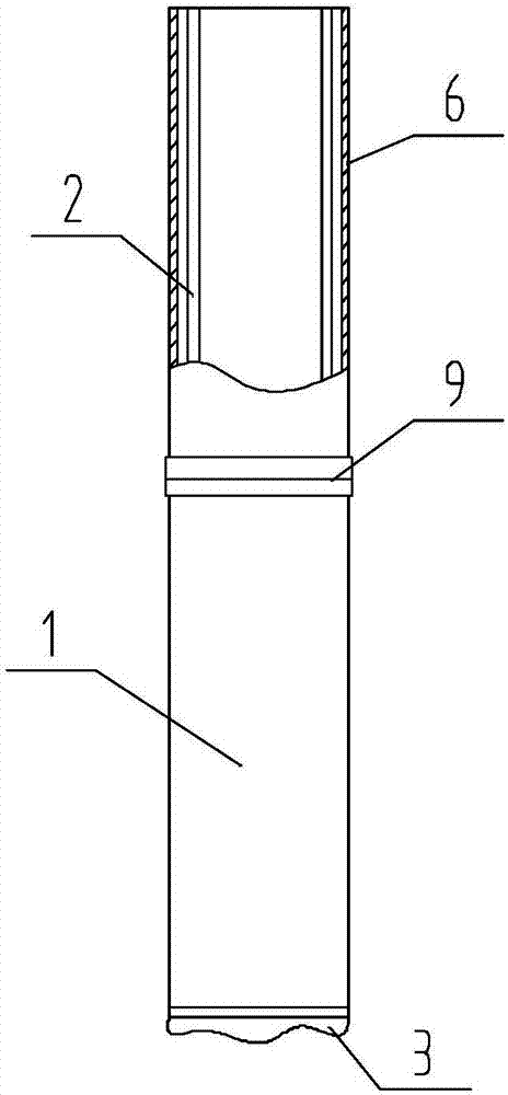
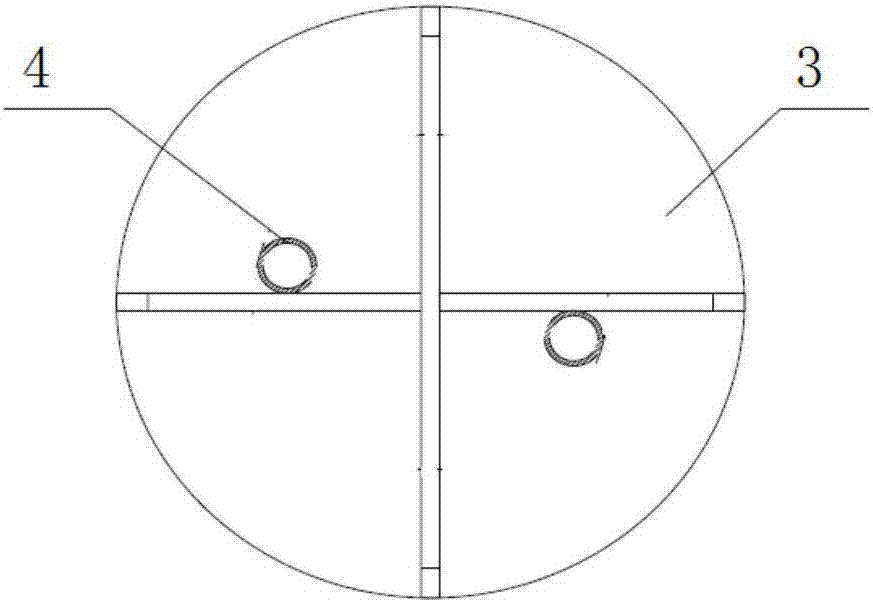
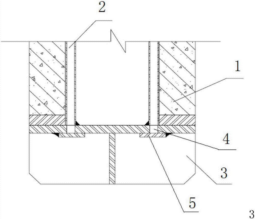
The invention provides a pipe pile with post-pressure-grouting grouting pipes. The pipe pile comprises a pipe pile body, the grouting pipes which are arranged in the pipe pile body and symmetrically arranged with the axis of the pipe pile body as the center and a steel pile point arranged at the lower end of the pipe pile body. Slurry discharge holes are formed in the positions, corresponding to the pouring pipes, on the steel pile point. Blocking plates which are used for covering the slurry discharge holes and can be jacked up by the grouting pressure are welded to the positions corresponding to the slurry discharge holes in a spot welding manner. The two grouting pipes are vertically arranged. The pipe pile body is formed by the multiple-joint butt joint. Each grouting pipe comprises multiple sections matched with the sections, corresponding to the grouting pipe, of the pipe pile in length. The portions, close to the joints of the pipe pile body, of the sections of the grouting pipes are connected through pipe joints. By the adoption of the pipe pile with the post-pressure-grouting grouting pipes, the single-pile bearing force of the prefabricated concrete pipe pile is improved effectively, the modulus of compression of foundation soil is increased, the settlement of a building is reduced, the pile length is reduced, the number of piles is reduced, the stability of the building is guaranteed, and the building cost is saved.

Description

technical field [0001] The invention belongs to the technical field of concrete prefabricated pipe pile engineering, and in particular relates to a pipe pile with a post-pressure grouting pipe and a construction method thereof. Background technique [0002] With the development of the city, the construction land is becoming more and more tense, the height of the building is also increasing, and the requirements for the bearing capacity of the foundation are also continuously increasing. At present, in order to meet the requirements of the bearing capacity of the foundation, most of the foundation treatment of small high-rise and high-rise buildings is made of concrete. The construction of prefabricated pipe piles and concrete prefabricated pipe piles is limited by the technology. They are generally used in clay, silt and soft soil layers, but the bearing capacity of clay, silt and soft soils is small, and the compression modulus is small. It can enter the strong weathered mu...

Claims


Application Information

Patent Timeline
Patent Type & Authority Applications(China)
IPC IPC(8): E02D5/22E02D15/04
CPCE02D5/22E02D15/04
Inventor 尹友非陈亚东赵建刚张生雨刘亮邢德强杨俊刚
Owner MCC TIANGONG GROUP
Why Eureka
Try Eureka