
A crank connecting rod mechanism piston reciprocating single-cylinder internal combustion engine

A crank connecting rod mechanism, internal combustion engine technology, applied in the direction of internal combustion piston engines, machines/engines, mechanical equipment, etc., can solve the problems of instantaneous response lag, high supercharging degree, engine can not adapt to cooling technical scheme and supercharging technical scheme, etc.

Active Publication Date: 2019-07-12
肖光宇
View PDF6 Cites 0 Cited by
  • Summary
  • Abstract
  • Description
  • Claims
  • Application Information

AI Technical Summary

Problems solved by technology

[0030] In order to improve the power-to-weight ratio of the engine, the existing technology mainly adopts the exhaust gas turbocharging method to realize it, but its biggest defect is that the instantaneous response lags, and it is difficult to achieve a higher supercharging degree (the increased power after supercharging is equal to the Ratio of unsupercharged power), it is difficult to apply to the largest and most widely used small and medium-sized engines, especially those used in vehicles; it is difficult to accurately control the amount and temperature of the supercharged air and its water vapor and Components of trace water mist in pressurized air
[0031] The structure and working system of the existing conventional engine cannot adapt to the application of the newly invented cooling technical solution and supercharging technical solution, and the existing structure and working system of the engine need to be modified and increased accordingly to form a new type of engine. Crank-and-rod piston reciprocating internal combustion engine

Method used


Image

  • A crank connecting rod mechanism piston reciprocating single-cylinder internal combustion engine
  • A crank connecting rod mechanism piston reciprocating single-cylinder internal combustion engine
  • A crank connecting rod mechanism piston reciprocating single-cylinder internal combustion engine

Examples


Embodiment Construction

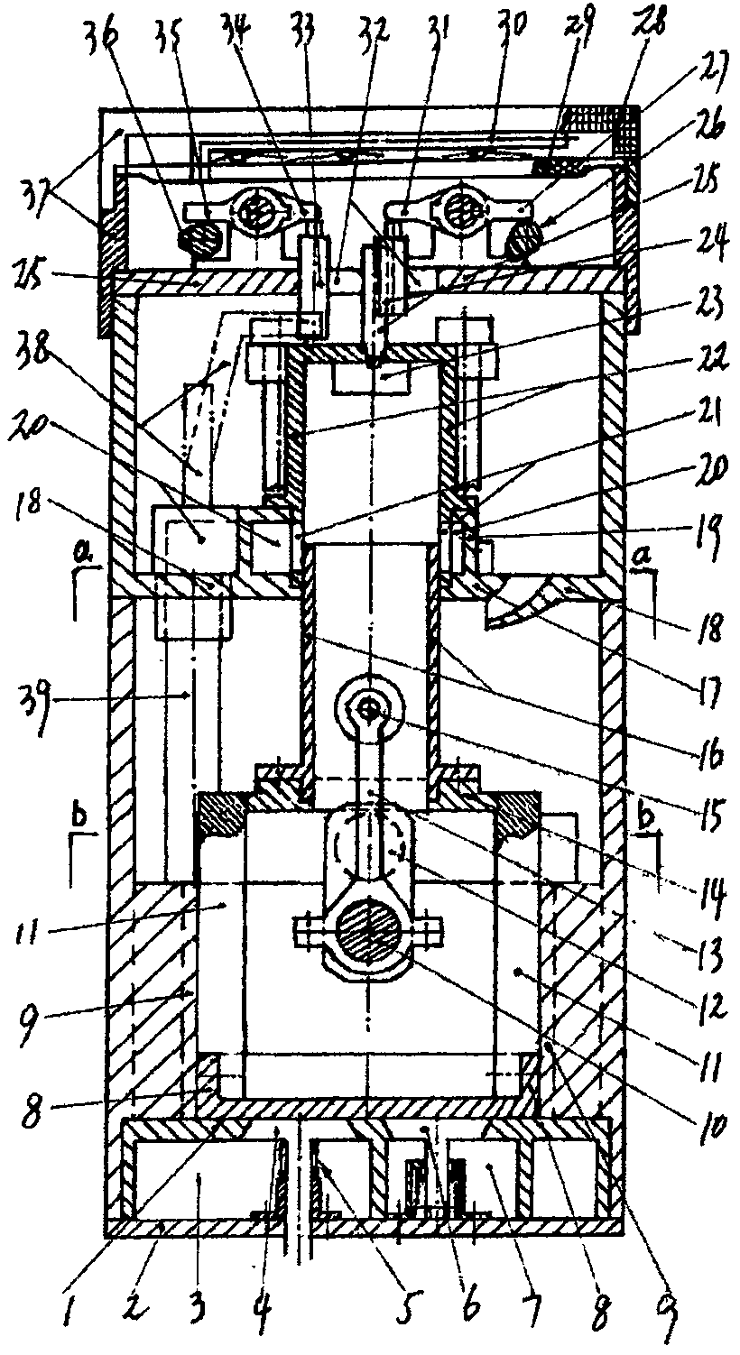
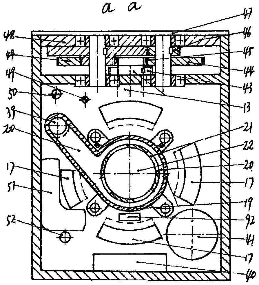
[0094] figure 1 combine Figure 5 Shown: the engine body is divided into upper and lower parts by the body diaphragm 18 and connected. The integrated control system is arranged on the top cover plate 25 of the engine. The energy recovery system is located at the rear of the engine.

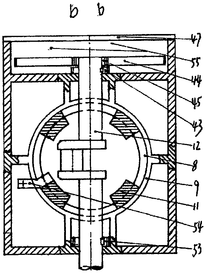
[0095] figure 1 , 3 , 5 shows: the supercharging mechanism is combined with the power mechanism, and is arranged in the middle of the lower part of the body. The supercharging mechanism frame is formed by connecting the upper and lower ends of the frame with frame columns 11. The upper end 14 of the supercharging frame is connected with the piston 16 of the engine cylinder, and the lower end Connect or directly make the booster cylinder piston 8; the booster cylinder piston diameter ≥ 2 times the engine cylinder piston diameter, the crank connecting rod mechanism is arranged in the booster frame, the small end of the connecting rod 14 is connected with the engine cylinder piston pin 15, and t...


PUM


Abstract

The invention discloses a piston reciprocating single-cylinder internal combustion engine with a crank-link mechanism. The piston reciprocating single-cylinder internal combustion engine is mainly characterized by comprising a supercharging frame and a secondary engine cylinder internal water spraying system; the supercharging frame is formed by a cylinder (11), an upper end and a lower end; the upper end (14) of the supercharging frame is connected with an engine cylinder piston (16), and the lower end of the supercharging frame is connected with a supercharging cylinder piston (8); the crank-link mechanism is placed in the a piston reciprocating supercharging mechanism in the supercharging frame and compounded with a power mechanism; and the secondary engine cylinder internal water spraying system comprises a pump water spraying nozzle (24), a rocker mechanism and a cam (26). The degree of supercharging of the supercharging mechanism approximates 4, and defects that in the prior art, turbocharging instantaneous reaction is lagged, the degree of supercharging is low, and the conventional turbocharging mechanism is difficult to be applied to a small engine are overcome; and the secondary engine cylinder internal water spraying system replaces a conventional cooling way, about 30% of fuel thermal efficiency loss taken away in the conventional cooling way is avoided, the effective thermal efficiency of the engine is about 70%, and besides, generation of various bad combustion pollutants is eliminated, and emission of a large amount of CO2 to the air is reduced.

Description

technical field [0001] The invention belongs to the field of internal combustion engines, and in particular relates to a technical solution for energy saving, decontamination and pressurization of a piston reciprocating internal combustion engine of a crank connecting rod mechanism. Background technique [0002] Due to the shackles of traditional ideas and cognition on the cooling of the engine device by the existing conventional internal combustion engine, it is theoretically wrong to identify a large amount of thermal efficiency loss caused by the existing cooling, and about 30% of the resulting fuel consumption The loss of thermal efficiency and the emission of a large amount of bad combustion pollutants and carbon dioxide into the atmosphere have long been taken for granted and turned a blind eye. To overcome this defect and deficiency, compared with conventional internal combustion engines, which are the most widely used and used in the largest amount, and whose fuel co...

Claims


Application Information

Patent Timeline
Patent Type & Authority Patents(China)
IPC IPC(8): F02B33/18F02B33/44F02M25/025F02M25/03F02M59/20F01L1/348F01L1/18F01M1/02F01N5/04F02B75/16
CPCF01L1/181F01L1/348F01M1/02F01M2001/023F01N5/04F02B33/18F02B33/44F02B75/16F02M25/025F02M25/03F02M59/20Y02T10/12
Inventor 肖光宇
Owner 肖光宇
Learn More