Elevator installed in existing building

A technology for buildings and elevators, which is applied to elevators, buildings, and building components in buildings. It can solve the problems of insufficient space utilization efficiency, large man-hour consumption, and prolonged residence time, so as to save installation and adjustment steps, The hoistway space is minimized and the structure is compact and reasonable

Pending Publication Date: 2017-10-17
XUANCHENG VALIN PRECISION TECH
View PDF6 Cites 4 Cited by
  • Summary
  • Abstract
  • Description
  • Claims
  • Application Information

AI Technical Summary

Problems solved by technology

[0002] As high-rises have only been widely popularized in the last ten years, elevators have also become popular. At present, there are still large-scale old residential buildings and small high-rise residential buildings without elevators. The layout of the residential area is compact and the supporting community services are lacking.
At the same time, these houses are mostly middle-aged and elderly people, and the lack of elevators brings a lot of inconvenience to their lives. The existing installation of elevators is to first install the steel structure shaft independently, and then extend the counterweight guide rail bracket in the shaft, install the guide rail bracket, and then Install the counterweight rail
The installation and adjustment of counterweight guide rails and brackets are cumbersome and consume a lot of man-hours. At the same time, since the steel structure is generally assembled with profiles, the width direction of the steel structure columns and crosspieces occupy the space of t

Method used


Image

  • Elevator installed in existing building
  • Elevator installed in existing building
  • Elevator installed in existing building

Examples


Example Embodiment

[0029] In order to deepen the understanding of the present invention, the present invention will be further described in detail with reference to the accompanying drawings and embodiments. The embodiments are only used to explain the present invention and do not limit the protection scope of the present invention.
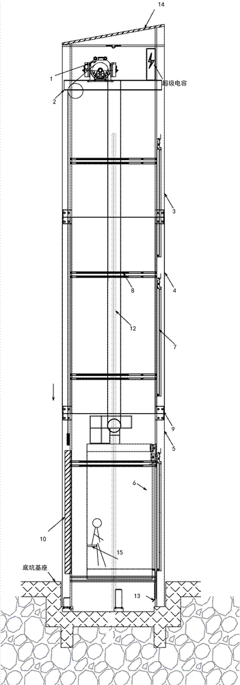
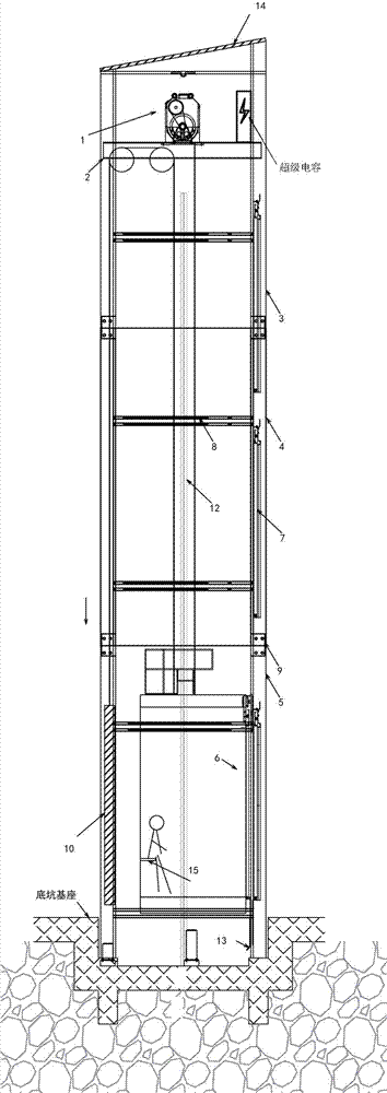
[0030] Such as Figure 1-12 As shown, the present invention is an existing building installation ladder. A bottom steel structure 5 is provided in the pit base, and the bottom pit is 600mm. Above the bottom steel structure 5, there is at least a middle section of steel. Section steel structure 4, preferably, the middle section steel structure 4 is one or two sections, and the installation ladder is composed of three to four sections as a whole. The bottom section steel structure is assembled into a frame structure during assembly and transportation, and the overall height is controlled at 6m Inside, the main guide rails are installed and fixed in place, the car, car f...


PUM

PropertyMeasurementUnit
Heightaaaaaaaaaa
Heightaaaaaaaaaa

Abstract

The invention discloses an elevator installed in an existing building. The inner portion of a base of a bottom pit is provided with a bottom section steel structure, the steel at the upper portion of the bottom section steel structure is provided with at least one section of middle section steel structure, and the upper portion of the middle section steel structure is provided with a top section steel structure. At least one upright column in the bottom section steel structure, at least one upright column in the middle section steel structure and at least one column in the top section steel structure are all provided with flanging of heavy auxiliary guide rail as integrated mineral powders. The bottom section steel structure, the middle section steel structure and the top section steel structure forms steel structure hoistway of the elevator, a carriage system is arranged in the steel structure hoistway through a main orbit, the upper end of the top section steel structure is provided with a mainframe and a plurality of guide wheels through a load bearing beam, and the carriage system moves up and down driven by the mainframe and the guide wheels. A portion of the steel structure is used as a counterweight rail, no guide rail support is needed, the elevator hoistway is manufactured by sections, the installation of the steel structure hoistway and the elevator is conducted at the same time at the site, time and effort are saved, and construction period is reduced.

Description

technical field [0001] The invention belongs to the technical field of elevator processing, and in particular relates to a ladder installed in an existing building. Background technique [0002] Since high-rise buildings have only been widely popularized in the last ten years, elevators have also become popular. At present, there are still large-scale old residential buildings and small high-rise buildings without elevators. The layout of the residential area is compact and the supporting community services are lacking. At the same time, these houses are mostly middle-aged and elderly people, and the lack of elevators brings a lot of inconvenience to their lives. The existing installation of elevators is to first install the steel structure shaft independently, and then extend the counterweight guide rail bracket in the shaft, install the guide rail bracket, and then Install the counterweight rail. The installation and adjustment of counterweight guide rails and brackets ar...

Claims


Application Information

Patent Timeline
IPC IPC(8): B66B9/00B66B11/02E04F17/00B66B17/12B66B7/00
CPCE04F17/005B66B7/00B66B9/00B66B11/0226B66B17/12
Inventor 黄业华陈海华葛志超宋云吴正涛
Owner XUANCHENG VALIN PRECISION TECH
Why Eureka
Try Eureka