Switch device compatible with access of single live wire or zero live wire and zero live line access detection circuit

A switching device and detection circuit technology, applied in lighting device, electric lamp circuit arrangement, electric light source, etc., can solve the problem of only or unable to install intelligent switching device, and achieve the effect of reducing power consumption, providing promotion rate, and multi-network work

Active Publication Date: 2017-10-17
NANJING IOT SENSOR TECH
View PDF5 Cites 9 Cited by
  • Summary
  • Abstract
  • Description
  • Claims
  • Application Information

AI Technical Summary

Problems solved by technology

[0004] The purpose of the present invention is to provide a switch device and a detection circuit compatible with a single live wire or a neutral live wire, aiming to solve the problem that there are only neutral wires and live wires in the switch box, or only live wires, so that it is impossible to install an intelligent switch device. And the technical problem that the switch device can detect whether the neutral line is connected

Method used


Image

  • Switch device compatible with access of single live wire or zero live wire and zero live line access detection circuit
  • Switch device compatible with access of single live wire or zero live wire and zero live line access detection circuit
  • Switch device compatible with access of single live wire or zero live wire and zero live line access detection circuit

Examples


specific Embodiment

[0052]Specific examples are as follows:

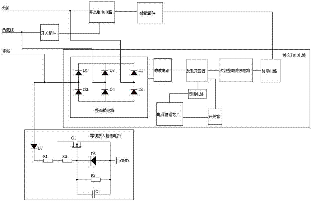
[0053] Take the flyback power supply as an example for the off-state power-taking circuit:

[0054] The first method: when the switch device is connected to the live line and the load line, when the light is turned on, the switch part is closed, the open state power-taking circuit works, and the obtained power is stored in the energy storage part to provide energy for the MCU chip.

[0055] When the light is turned off, the switch part is disconnected, and the off-state power-taking circuit works. At this time, the input of the off-state power-taking circuit is composed of live wire and load line, and the rectifier composed of diodes D1, D2, D3, D4, D5, and D6 The bridge circuit, the rectifier bridge circuit manages the alternating current into direct current, and the filter circuit filters the direct current. The flyback transformer, power management chip and switch tube are responsible for energy conversion. The feedback circuit sa...

Embodiment 2

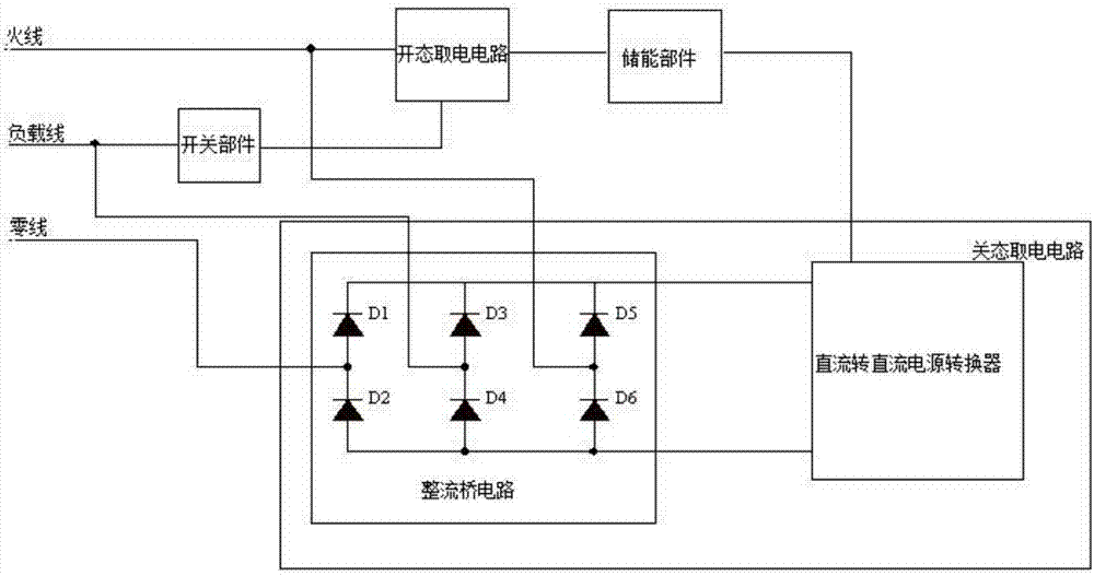
[0061] In this embodiment, a switch device compatible with single live wire or neutral live wire is used as an example:

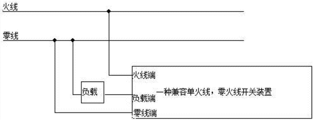
[0062] Such as Figure 4 As shown, when the user connects the switch device to the cassette, if the cassette only has live wires and load wires, connect the live wire and load wire to the switch device. At this time, the neutral line detection circuit does not work, and the MCU chip detects until the switchgear is in single live wire mode of operation.

[0063] Such as Figure 5 As shown, when the user connects the switch device to the cassette, if there are live wires, neutral wires and load wires in the cassette at the same time, the three wires can be connected to the corresponding terminals of the switch device at the same time. At this time, the neutral wire Through the diode D7, the Zener diode D8 is charged, so that the switch tube Q1 is turned on, and the drain of Q1 is pulled down to the ground. The MCU chip detects that the switch device is in a...

Embodiment 3

[0064] Embodiment 3 also provides a neutral line access detection circuit:

[0065] The zero line detection circuit is composed of diodes D7, D8, resistors R1, R2, R3, capacitor C1, and switch tube Q1. The diode D7 sorts the alternating current into direct current, and the resistors R1 and R2 are used to reduce system power consumption; the resistor R3 , Capacitor C1 and diode D8 form a voltage stabilizing circuit; the gate voltage of the switching tube Q1 is stable above the conduction threshold voltage of Q1, the drain of the switching tube Q1 is connected to the MCU chip, and the source is connected to the system ground signal, so When the switching device is connected to the neutral line, the gate voltage of the switching tube Q1 reaches its conduction threshold, then Q1 is turned on, the drain voltage is pulled to the ground, and the MCU chip detects the presence of the neutral line.

[0066] If the switch device does not detect the existence of the neutral line, the MCU ...


PUM


Abstract

The invention discloses a switch device compatible with access of a single live wire or a zero live wire and a zero live line access detection circuit. The switch device compatible with access of the single live wire or the zero live wire comprises an on-state electricity-taking circuit, an off-state electricity-taking circuit, an energy storage member and a switch member; the fire live line is connected to the on-state electricity-taking circuit; the on-state electricity-taking circuit is connected to the switch member and the energy storage member; the load line is connected to the switch member; the fire live line, the load line and the zero live line are respectively connected to the off-state electricity-taking circuit; the off-state electricity-taking circuit is connected to the energy storage member; the on-state electricity-taking circuit is used for taking stable energy when the switch member is in a conductive state and storing the stable energy in the energy storage member; the off-state electricity-taking circuit comprises a power supply converter and a rectifier bridge circuit consisting of multiple diodes including D1,D2,D3,D4,D5 and D6; and the switch member is used for switching on and off of a load line which is connected to the switch device. The zero live line access detection circuit can detect whether the zero live line accesses the switch device, and the energy storage device stores energy which is taken by the on-state electricity-taking circuit and supplies energy to an MCU chip.

Description

technical field [0001] The invention belongs to the technical field of a single live wire switch, and relates to a switch device compatible with a zero live wire or a single live wire, in particular to a light switching device and a detection circuit compatible with a single live wire or a neutral live wire. Background technique [0002] With the continuous advancement of science and technology and the improvement of people's requirements for living standards, the application of smart home equipment is becoming more and more popular. As an indispensable part of smart home equipment, smart single live wire switches have been more and more widely used. Through smart The single live wire switch can control the power on and off of the smart home equipment by receiving the control command. [0003] Some of the existing switch cassettes only have the neutral wire and the live wire, and some only have the live wire, which causes the problem that they cannot all be compatible with t...

Claims


Application Information

Patent Timeline
Patent Type & Authority Applications(China)
IPC IPC(8): H05B37/02
CPCH05B47/10
Inventor 张伟钟任朱俊岗朱峰朱俊岭余建美
Owner NANJING IOT SENSOR TECH
Why Eureka
Try Eureka