
Automatic chamfer milling equipment

A milling and chamfering, automatic technology, applied in milling machine equipment, milling machine equipment details, metal processing equipment and other directions, can solve problems such as increased workload of workers, workpiece pits or burrs, insufficient process accuracy, etc., to achieve continuous consistency improvement, The effect of improving workpiece quality and speeding up production rate

Active Publication Date: 2017-10-20
ZHEJIANG CHUANGNENG MACHINERY
View PDF5 Cites 1 Cited by
  • Summary
  • Abstract
  • Description
  • Claims
  • Application Information

AI Technical Summary

Problems solved by technology

[0002] As we all know, milling and chamfering equipment usually consists of a vibrating feeding tray and a machine tool. The vibrating feeding tray is a feeding device that is automatically oriented and sorted. Its working purpose is to automatically and orderly arrange disordered workpieces in a neat and accurate manner through vibration. In the next process, especially the arrangement of small workpieces that are difficult to operate manually, and the arrangement of ultra-small workpieces, workers usually need to supply a part of workpieces to the vibrating feeding tray at regular intervals in order to prevent the vibrating feeding tray from being blocked during operation. Make the vibrating feeding tray run more efficiently, but this method requires workers to refill frequently, which greatly increases the workload of workers
[0003] Existing machine tools usually need to use a wrench to clamp the workpiece during the clamping process to ensure that the workpiece can be kept stable during processing. However, manual clamping of the workpiece not only increases the number of workers, but also reduces labor efficiency. Increase the probability of operating errors, and in the process of operation, a single process structure is usually adopted, which may easily lead to insufficient accuracy of the entire process, resulting in pits or burrs on the processed workpiece

Method used


Image

  • Automatic chamfer milling equipment
  • Automatic chamfer milling equipment
  • Automatic chamfer milling equipment

Examples


Embodiment 1

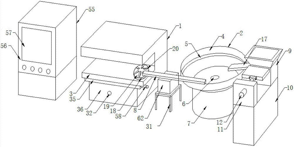
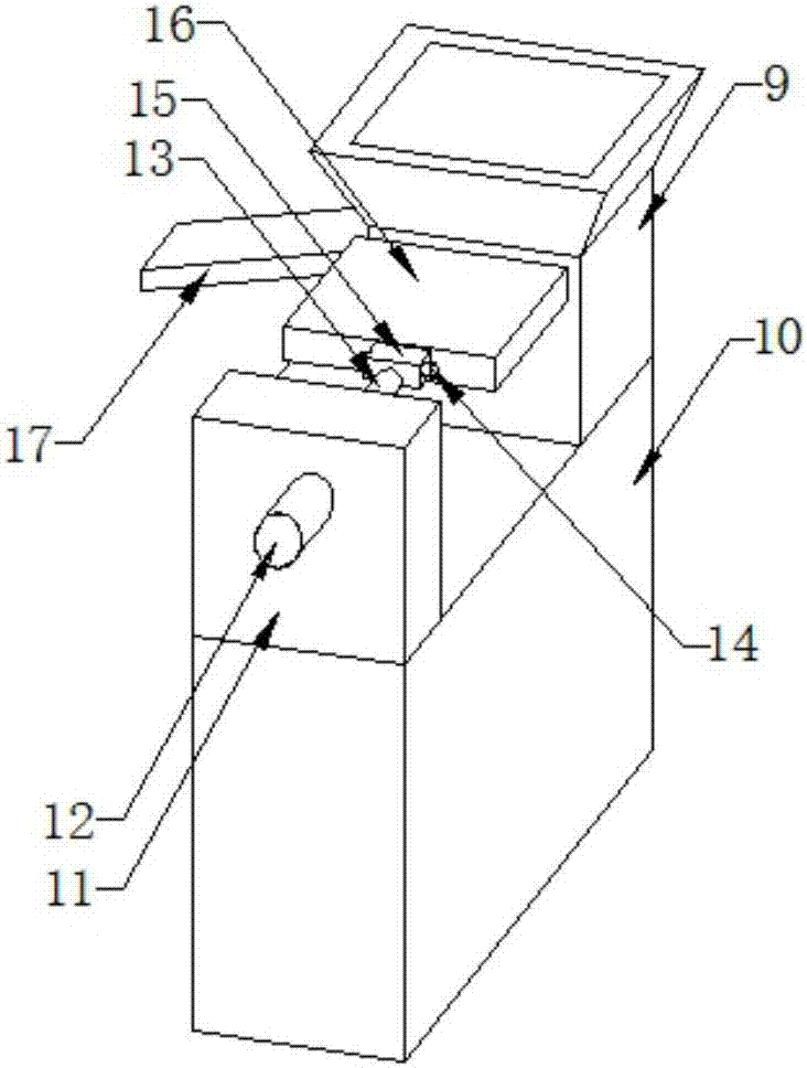
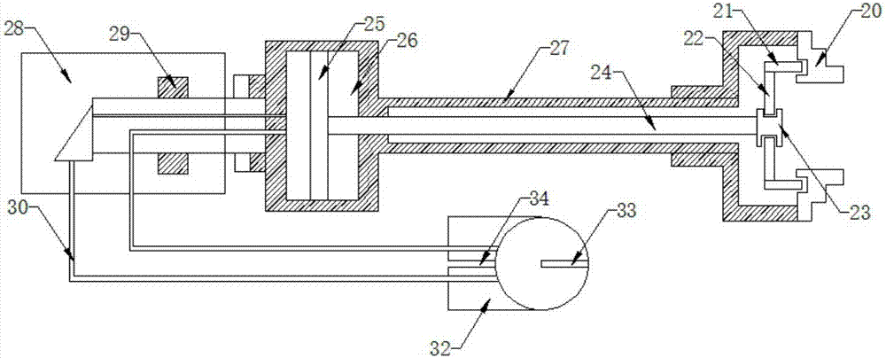
[0022] Such as Figure 1-5As shown, the present invention provides an automatic milling and chamfering equipment, including an automatic milling and chamfering machine tool 1 and a vibrating feeding tray 2. The top plate 4, the top plate 4 is provided with a directional rail 5, the center of the directional rail 5 is provided with a bearing 6, the bottom of the top plate 4 is provided with a chassis 7, the chassis 7 is driven by an electromagnet, and one end of the directional rail 5 is connected There is a linear feeder 8 and the linear feeder 8 leads to the workbench 3 of the automatic milling and chamfering machine tool 1. One side of the vibrating feeding tray 2 is provided with a feeder 9, and the bottom of the feeder 9 is provided with a fixed seat 10. One end of seat 10 top is fixed with fixed plate 11, and fixed plate 11 is provided with the hydraulic driver 12 that runs through fixed plate 11 transversely, and one end of hydraulic driver 12 is connected with telescopi...


PUM


Abstract

The invention discloses automatic chamfer milling equipment. The equipment comprises an automatic chamfer milling machine tool and a vibrating feeding disk; one end of the vibrating feeding disk is connected with a linear feeder; the linear feeder is straightly led to a workbench of the automatic chamfer milling machine tool; a material bin is arranged on one side of the vibrating feeding disk; a hydraulic driver is arranged on the material bin; one end of the hydraulic driver is connected with a telescopic rod; a moving plate penetrating through the side wall of the material bin is arranged on one side of the telescopic rod; a discharging port is formed in one side, different from the direction of the moving plate, of the material bin and is located above the vibrating feeding disk; an automatic six-claw clamping structure is arranged on the workbench; a sliding seat is arranged at the bottom, in the direction of the linear feeder, of the workbench; a base is arranged at the bottom of the sliding seat; and a plane milling head, a chamfering milling head, a hole drilling milling head and a hole milling head are sequentially arranged at the top, in the direction of the linear feeder, of the workbench. With the equipment, the number of workers is reduced, the labor efficiency is improved, operation errors are reduced, the production rate is increased, and the workpiece quality is improved.

Description

technical field [0001] The invention relates to a chamfering equipment, in particular to an automatic chamfering equipment. Background technique [0002] As we all know, milling and chamfering equipment usually consists of a vibrating feeding tray and a machine tool. The vibrating feeding tray is a feeding device that is automatically oriented and sorted. Its working purpose is to automatically and orderly arrange disordered workpieces in a neat and accurate manner through vibration. In the next process, especially the arrangement of small workpieces that are difficult to operate manually, and the arrangement of ultra-small workpieces, workers usually need to supply a part of workpieces to the vibrating feeding tray at regular intervals in order to prevent the vibrating feeding tray from being blocked during operation. Make the vibrating feeding tray run more efficiently, but this method requires workers to frequently feed, which greatly increases the workload of workers. ...

Claims


Application Information

Patent Timeline
Patent Type & Authority Applications(China)
IPC IPC(8): B23Q7/00B23Q7/04B23Q7/10B23C9/00
CPCB23C9/005B23Q7/00B23Q7/04B23Q7/10Y02P70/10
Inventor 陶荣明甘为军周国斌
Owner ZHEJIANG CHUANGNENG MACHINERY
Features
  • Generate Ideas
  • Intellectual Property
  • Life Sciences
  • Materials
  • Tech Scout
  • Unparalleled Data Quality
  • Higher Quality Content
  • 60% Fewer Hallucinations
Learn More