Gas turbine combustor

A technology of gas turbine and burner, applied in the direction of burner, burner, burner cooling, etc., can solve the problems of excessive temperature rise and reduce the reliability of gas turbine burner, and achieve the goal of suppressing excessive temperature rise and ensuring reliability. Effect

Inactive Publication Date: 2017-10-20
MITSUBISHI HITACHIPOWER SYST LTD
View PDF7 Cites 9 Cited by
  • Summary
  • Abstract
  • Description
  • Claims
  • Application Information

AI Technical Summary

Problems solved by technology

[0005] However, when switching from start-up fuel to coal gasification gas, the flames generated by each fuel interfere with each other, and the temperature of the structure of the gas turbine combustor may rise excessively, which may reduce the reliability of the gas turbine combustor

Method used


Image

  • Gas turbine combustor
  • Gas turbine combustor
  • Gas turbine combustor

Examples


no. 1 approach

[0045] (structure)

[0046] 1. Complete set of gas turbine equipment

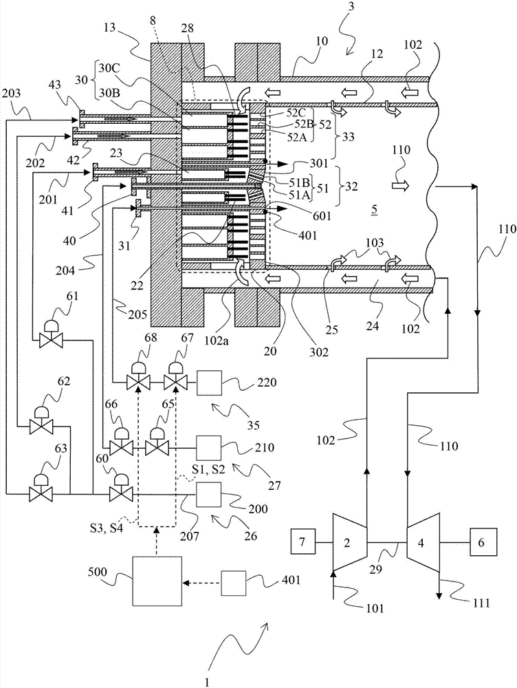
[0047] figure 1 A configuration example of a gas turbine plant to which a gas turbine combustor (hereinafter referred to as a combustor) according to the present embodiment is applied is shown. Such as figure 1 As shown, the gas turbine plant 1 includes a compressor (air compressor) 2 , a combustor 3 , a turbine 4 , a generator 6 , and a starter motor 7 .

[0048] The compressor 2 is started by the starting motor 7 , compresses the air 101 sucked from the atmosphere through an air intake unit (not shown), generates high-pressure compressed air 102 , and supplies it to the combustor 3 . The combustor 3 mixes and burns the compressed air 102 supplied from the compressor 2 and the fuel supplied from the fuel system 26 (described later), generates high-temperature combustion gas 110 , and supplies it to the turbine 4 . The turbine 4 is driven by the expansion of the combustion gas 110 supplied from the comb...

no. 2 approach

[0103] (structure)

[0104] Figure 9 A structural example of a gas turbine plant to which the combustor according to the present embodiment is applied is shown. exist Figure 9 In , the same reference numerals are assigned to the same parts as those in the first embodiment described above, and explanations thereof are appropriately omitted.

[0105] In this embodiment, the cooling system 35 is different from the first embodiment in that it further includes a cooling pipe 206 , a cooling nozzle 34 , a thermocouple 402 , and a cooling hole 602 . Other points are the same as the first embodiment.

[0106] Such as Figure 9 As shown, the cooling pipe 206 branches from the cooling pipe 205 and connects the coolant supply source 220 and the cooling nozzle 34 . The cooling nozzle 34 is connected to the cooling hole 602 . The coolant introduced from the coolant supply source 220 to the cooling nozzle 34 via the cooling pipe 206 is injected into the combustion chamber 5 via the ...


PUM


Abstract

The invention relates to a gas turbine combustor, being able to suppress excessive temperature rise of a structure of the gas turbine combustor and ensure the reliability of the gas turbine combustor. In a gas turbine combustor (3) of the present invention, an air hole plate 20 includes a center air hole group 51 configured from a plurality of air holes (51A) and (51 B) and a plurality of outer circumferential air hole groups (52) configured from a plurality of air holes (52A, 52B), and (52C) and formed to surround the center air hole group (51). The gas turbine combustor (3) includes a hole part (601) and a temperature sensor (401) provided on the air hole plate (20) to be located in a region surrounded by two outer circumferential air hole groups (52) adjacent to each other and the center air hole group (51), a supply source (220) of coolant, a cooling pipeline (205) that connects the hole part (601) and the supply source (220), valves (67, 68) provided in the cooling pipeline (205), and a control system (500) that drives the valves (67, 68) on the basis of a measured value of the temperature sensor (401).

Description

technical field [0001] The invention relates to a gas turbine combustor. Background technique [0002] In recent years, from the perspective of preventing the greenhouse effect and effectively utilizing resources, etc., there have been opportunities to use hydrogen-containing gases such as coke oven gas incidentally produced in ironworks and waste gas incidentally produced in oil refineries as fuel for gas turbine combustors increased. Carbon dioxide (CO 2 ) has less emissions and effectively prevents the greenhouse effect. In addition, in a coal gasification combined power plant (IGCC plant) that gasifies coal, which is an abundant resource, to generate electricity, recovery / storage of the amount of carbon contained in hydrogen-containing fuel (coal gasification gas) supplied to the gas turbine combustor is installed. system (CCS), further reducing CO 2 emissions. [0003] However, since the hydrogen in the hydrogen-containing fuel has a wide combustible range and a hi...

Claims


Application Information

Patent Timeline
Patent Type & Authority Applications(China)
IPC IPC(8): F23R3/28
CPCF23R3/283F23N5/107F23N5/242F23R3/34F23R3/36F23C2900/99011F23D2208/10F23D2214/00F23R2900/00005Y02E20/16Y02E20/18F23N2241/20F02C6/00F23R3/06F23R3/42F23R2900/03045F05D2240/35F23R3/002
Inventor 浅井智广林明典穐山恭大
Owner MITSUBISHI HITACHIPOWER SYST LTD
Why Eureka
Try Eureka