Automatic pole aligning coding sensor

A technology of sensors and magnetic encoders, applied in the field of sensors, can solve the problems that the permanent magnet synchronous motor of the controller cannot be plug-and-play, the controller or the permanent magnet synchronous motor cannot be interchanged, and the increase in manufacturing man-hours, etc., achieves the realization method Ingenious, low cost, effect of reducing installation time

Active Publication Date: 2017-10-20
SHANGHAI JUNQIAN SENSING TECH CO LTD
View PDF8 Cites 2 Cited by
  • Summary
  • Abstract
  • Description
  • Claims
  • Application Information

AI Technical Summary

Problems solved by technology

[0005] 1. Since the angle between the position signal output by the sensor and the actual position of the rotor is not uniform, it is necessary to increase the process of recording the angle data in the manufacturing process, and it is necessary to equip special laser marking equipment or other marking equipment. Not only increased cost but also increased manufacturing man-hours
[0006] 2. Due to the inconsistency of the included angle, the system debugger needs to input the included angle data on the nameplate of the permanent magnet synchronous motor into the controller one by one, which increases the complexity of the use process
[0007] 3. After inputting the angle data of the corresponding permanent magnet synchronous motor in the controller, the controller and the permanent magnet synchronous motor can only correspond one by one, and cannot be interchanged with other controllers or permanent magnet synchronous motors
[0008] 4. During maintenance, due to the difference in the included angle data, neither the controller nor the permanent magnet synchronous motor can realize plug and play, and professional technicians are required to complete the included angle data input

Method used


Image

  • Automatic pole aligning coding sensor
  • Automatic pole aligning coding sensor
  • Automatic pole aligning coding sensor

Examples


Embodiment Construction

[0031] In order to make the technical means, creative features, goals and effects achieved by the present invention easy to understand, the present invention will be further described below in conjunction with specific illustrations.

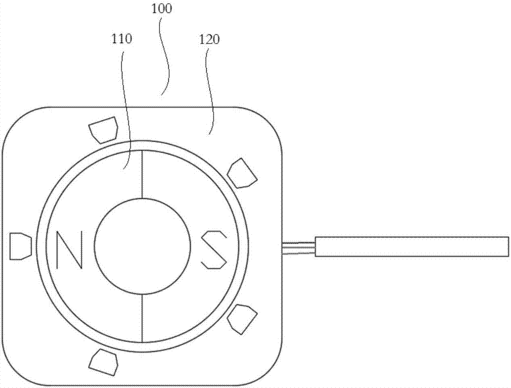
[0032] see figure 1 , which shows the structural schematic diagram of the sensor with automatic pole alignment function provided by this scheme. The sensor is used in a permanent magnet synchronous motor, which can realize automatic pole alignment and accurately detect the rotor position.

[0033] It can be seen from the figure that the automatic pole alignment sensor 100 mainly includes two parts: a magnetic encoder 110 and a sensor body assembly 120 .

[0034] Among them, the magnetic encoder 110 is used to connect the target object to be measured (such as the rotor in the permanent magnet synchronous motor), which is rotatably arranged relative to the sensor body assembly 120 and generates a continuous magnetic field which changes periodical...


PUM


Abstract

The invention discloses an automatic pole aligning coding sensor which comprises a magnetic coder and a sensor body assembly. The magnetic coder is rotatably arranged relative to the sensor body assembly and generates a periodically changing continuous magnetic field. The sensor body assembly acquires the changing magnetic field which is generated by the rotating magnetic coder from different directions and correspondingly outputs an absolute amount type signal. Furthermore pole alignment calculation can be performed according to the synchronously acquired signal. The sensor with an automatic pole aligning function has advantages of greatly simplifying sensor mounting of a permanent magnet synchronous electric machine, greatly shortening debugging time in a subsequent using process of the permanent magnet synchronous electric machine, and reducing maintenance difficulty.

Description

technical field [0001] The invention relates to sensors, in particular sensors designed to detect the position of a rotor. Background technique [0002] After the permanent magnet synchronous motor is installed with a sensor for detecting the rotor position, the sensor needs to be calibrated to detect the angle between the position signal output by the sensor and the actual position of the rotor. [0003] The calibration action is usually detected by the angle detection device after the permanent magnet synchronous motor is installed, and finally the angle between the position signal output by the sensor and the actual position of the rotor is obtained. This angle data will be used to control the permanent magnet synchronous motor. in the controller. Therefore, it is necessary to engrave the included angle data on the nameplate of the permanent magnet synchronous motor by means of laser engraving or the like. [0004] When debugging the controller and the permanent magnet ...

Claims


Application Information

Patent Timeline
Patent Type & Authority Applications(China)
IPC IPC(8): G01D5/14
CPCG01D5/145
Inventor 姜泽明
Owner SHANGHAI JUNQIAN SENSING TECH CO LTD
Why Eureka
Try Eureka