MEMS fluid density sensor chip based on in-plane resonance and preparation method thereof

A sensor chip and fluid density technology, which is applied in the field of MEMS sensors, can solve the problems of limited density sensor applicable fluid range, lower resonance frequency, poor precision, etc., and achieve good measurement accuracy and sensitivity, reduced fluid damping force, and accurate measurement. Effect

Active Publication Date: 2017-10-20
XI AN JIAOTONG UNIV
View PDF8 Cites 1 Cited by
  • Summary
  • Abstract
  • Description
  • Claims
  • Application Information

AI Technical Summary

Problems solved by technology

However, with the advancement of science and technology and the increasingly complex engineering requirements, the requirements for the density measurement range and measurement accuracy are getting higher and higher, and the structural characteristics of the cantilever beam as a resonant device make its vibration direction perpendicular to the fluid surface. The contact area of ​​the fluid damping is large, and the damping between the fluid and the fluid is pressure-film damping. Therefore, in the higher-density fluid, the additional mass of the fluid attached to the surface of the cantilever beam increases, and the damping increases, which reduces the resonance performance of the cantilever beam, including quality factor reduction. Small size, lower resonance frequency, etc., lead to low sensitivity and poor accuracy of fluid density measurement, which limits the applicable fluid range of the density sensor, and cannot meet the actual diverse and complex engineering needs

Method used


Image

  • MEMS fluid density sensor chip based on in-plane resonance and preparation method thereof
  • MEMS fluid density sensor chip based on in-plane resonance and preparation method thereof
  • MEMS fluid density sensor chip based on in-plane resonance and preparation method thereof

Examples


Embodiment Construction

[0032] The preferred implementation of the present invention will be further described in detail below in conjunction with the accompanying drawings and through examples.

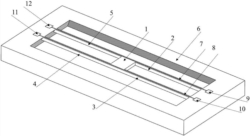
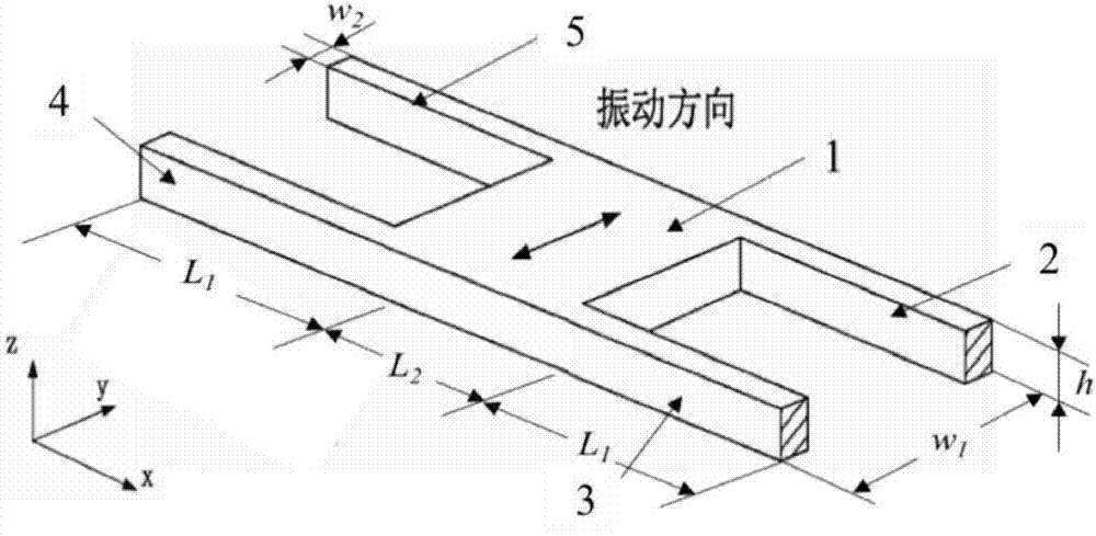
[0033] figure 1 It is a schematic diagram of the structure principle of the present invention. Depend on figure 1 It can be seen that a MEMS fluid density sensor chip based on in-plane resonance in the present invention includes an H-type silicon micro-double-terminal fixed beam structure and a silicon substrate 6 based on the vibration principle; the H-type silicon micro-double-terminal fixed beam structure includes a vibrator 1 , elastic fixed support beams 2-5, wires 7-8, and pads 9-12; the density sensor chip can realize in-plane vibration, and there is a synovial film damping between the measured fluid, which significantly reduces the fluid damping force and improves The measurement range, measurement accuracy and stability of the density sensor.

[0034] A magnet is added to the bottom of the silic...


PUM


Abstract

The invention discloses a MEMS fluid density sensor chip based on in-plane resonance and a preparation method thereof. The chip comprises a silicon substrate, four elastic fixed support beams and an intermediate vibrator. Two leads along the length direction of the silicon substrate are respectively arranged on the fixed support beams in two sides of the vibrator. A magnet at the bottom of the chip is used for providing a constant magnetic field. The direction of the magnetic induction line is perpendicular to the chip plane. Each one of the leads is applied with sinusoidal alternating currents having a certain frequency and the lead carries out in-plane vibration under action of an alternating Lorentz force on the fixed support beams so that the vibrator and the fixed support beams in the other side are driven to produce forced vibration and the other lead cuts the magnetic induction line and produces the induced electromotive force. The H-type silicon micro-double-end fixed support beam structure is immersed in the fluid to be detected and the frequency of the sinusoidal alternating current is changed so that fixed support beam resonance is produced. According to the amplitude of the output of the induced electromotive force, resonance frequency of the fixed support beams in the detected fluid is acquired. Through change of the fixed support beam resonant frequencies in different fluids, fluid density can be measured.

Description

technical field [0001] The present invention relates to the field of MEMS (Micro Electromechanical Systems, micro-mechanical electronic systems) sensors, more specifically, to a MEMS fluid density sensor chip based on in-plane resonance and a preparation method thereof. Background technique [0002] Density is one of the basic thermal properties of fluids. The high-precision, real-time online measurement of fluid density has a wide range of applications in petrochemical, biomedical, aerospace and scientific research fields. With the continuous development of MEMS technology and processing technology, the fluid density sensor based on MEMS technology has the advantages of small size, fast response, easy integration, high sensitivity, etc., and has been paid more and more attention in many fields. Among them, the types of density sensor sensitive components mainly include resonant beams, resonant plates, vibrating tubes, vibrating membranes, etc., and the cantilever beam based...

Claims


Application Information

Patent Timeline
IPC IPC(8): G01N9/24B81B7/02
Inventor 赵立波胡英杰黄琳雅李支康赵玉龙蒋庄德
Owner XI AN JIAOTONG UNIV
Why Eureka
Try Eureka