
Short pulse amplitude measurement method based on multiple times of pulse peak keeping, and implementation circuit

A peak hold and multiple pulse technology, applied in pulse processing, pulse shaping, pulse technology, etc., can solve the problems of expensive chips, inability to charge energy storage capacitors, and less energy carried by nanosecond-level narrow pulses. The noise ratio is too low, the data processing is simple, and the effect of avoiding noise

Active Publication Date: 2017-10-20
TANWAY TECH (BEIJING) CO LTD
View PDF8 Cites 6 Cited by
  • Summary
  • Abstract
  • Description
  • Claims
  • Application Information

AI Technical Summary

Problems solved by technology

[0003] The method disclosed in the prior art to directly obtain the peak intensity of nanosecond-level short pulses is to use a high-speed analog-to-digital converter (AD) with a bandwidth of GHz to sample the echo pulses. However, GHz-level high-speed analog-to-digital converter chips are expensive and corresponding The digital processing circuit design of the complex
Another indirect method disclosed in the prior art is to use a peak hold circuit to keep the peak voltage of the short pulse signal as a DC voltage. During the peak voltage hold period, a low-speed analog-to-digital converter is used to sample the constant level. However, due to Nanosecond-level narrow pulses carry less energy, and generally cannot effectively charge the energy storage capacitor in the peak hold circuit
Amplifying short nanosecond pulses can increase the energy carried by the pulses, but the requirements for the gain-bandwidth product of the amplification link are relatively high, and additional noise will be introduced, which will cause the instability of the post-stage peak hold circuit
Therefore, the traditional peak-and-hold circuit is not suitable for short nanosecond pulses

Method used


Image

  • Short pulse amplitude measurement method based on multiple times of pulse peak keeping, and implementation circuit
  • Short pulse amplitude measurement method based on multiple times of pulse peak keeping, and implementation circuit
  • Short pulse amplitude measurement method based on multiple times of pulse peak keeping, and implementation circuit

Examples


Embodiment Construction

[0018] The present invention will be described in detail below in conjunction with the accompanying drawings. However, it should be understood that the accompanying drawings are provided only for better understanding of the present invention, and they should not be construed as limiting the present invention.

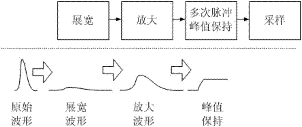
[0019] like figure 1 As shown, the short pulse amplitude measurement method based on multiple pulse peak hold provided by the present invention includes the following contents:

[0020] 1. To stretch the pulse width of the measured nanosecond narrow pulse.

[0021] The purpose of stretching the measured nanosecond-level narrow pulse is to increase the energy carried by the nanosecond-level narrow pulse. About 100 times of that (taking this as an example, the stretching multiple can be determined according to the actual usage), at this time, the amplitude of the nanosecond-level narrow pulse will decrease accordingly. Pulse stretching can be realized by using a tradit...


PUM


Abstract

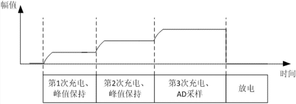
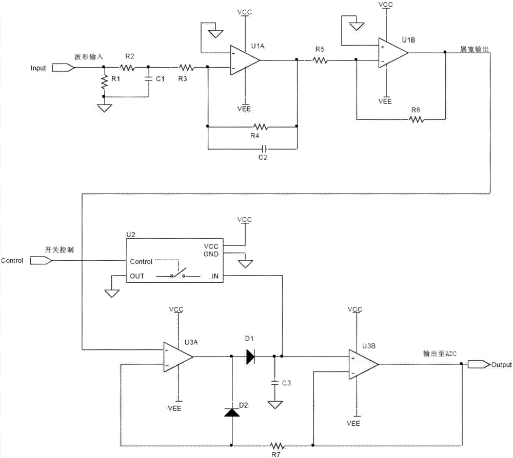
The invention relates to a short pulse amplitude measurement method based on multiple times of pulse peak keeping, and an implementation circuit. The method comprises the following steps: 1) performing pulse width expansion on a measured nanosecond level narrow pulse; 2) performing amplitude amplification on the expanded pulse signal; and 3) charging an energy storage capacitor for multiple times by using a waveform after the multiple times of pulse peak keeping to obtain the amplitude information of the nanosecond level narrow pulse. According to the short pulse amplitude measurement method, the energy storage capacitor is charged for multiple times by using multiple expanded and amplified signals, the pulse peak keeping is performed, which is equivalent to amplifying the energy of the measured nanosecond level narrow pulse, the noise of echo can also be avoided, the problems of insufficient nanosecond level narrow expansion and low signal to noise ratio are solved, and the short pulse amplitude measurement method can be widely used in the nanosecond narrow pulse peak keep.

Description

technical field [0001] The invention relates to a short pulse amplitude measurement method based on multiple pulse peak hold and a realization circuit, and relates to the technical field of laser ranging. Background technique [0002] The pulse laser ranging system based on the time-of-flight method or the laser pulse of the three-dimensional laser radar system is usually only a few nanoseconds. Obtaining the intensity information of the echo pulse is a necessary prerequisite for controlling the gain amplification and obtaining the gray level information of the target. [0003] The method disclosed in the prior art to directly obtain the peak intensity of nanosecond-level short pulses is to use a high-speed analog-to-digital converter (AD) with a bandwidth of GHz to sample the echo pulses. However, GHz-level high-speed analog-to-digital converter chips are expensive and corresponding The design of the digital processing circuit is complex. Another indirect method disclosed ...

Claims


Application Information

Patent Timeline
IPC IPC(8): H03K5/1532H03K5/04
CPCH03K5/04H03K5/1532
Inventor 吴冠豪
Owner TANWAY TECH (BEIJING) CO LTD
Learn More