Close-contact wireless speaker
A wireless speaker, close-range technology, applied in transducer circuits, frequency/directional characteristic devices, sensors, etc., can solve the problems of increasing the power consumption of the speaker itself and mobile devices, difficulty, and complicated operation.
- Summary
- Abstract
- Description
- Claims
- Application Information
AI Technical Summary
Problems solved by technology
Method used
Image
Examples
Embodiment 1
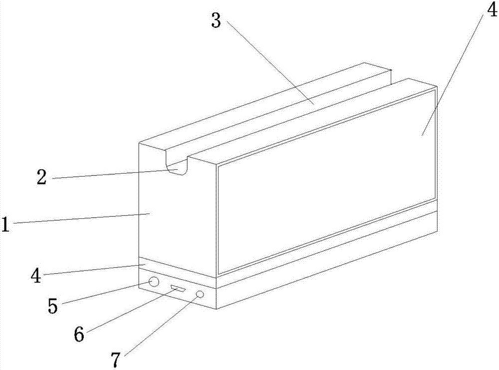
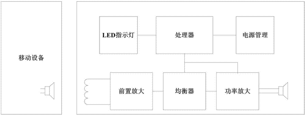
[0020] to combine figure 1 and figure 2 , a close-contact wireless speaker, including a box body 1, a U-shaped through groove 2 is opened on the upper surface of the box body 1, and the two sides of the U-shaped through groove 2 are magnetic induction areas 3; the two long sides of the box body 1 are provided with There is a speaker area 4, a wide side of the box body 1 is provided with an external interface area, the external interface area includes a power switch 5, a Micro USB interface 6 and a 3.5mm headphone jack 7; a circle of LED indicator lights 4 is provided on the surface of the box body 1, and the LED The indicator light 4 is located between the speaker area 4 and the external interface area; a circuit board is arranged inside the box body 1, and the circuit board includes a preamplifier module, an equalizer module, a power amplifier module, a processor module and a power management module.
[0021] The width and height of the U-shaped channel 2 are 2 cm, so that ...
Embodiment 2
[0026] to combine figure 1 and figure 2 , explaining how the speaker works.
[0027] Most of the speakers of mobile devices are electromagnetic moving coil, generally composed of magnets, coils, diaphragms, etc. When the speaker is energized, the changing current passes through the coil to generate a changing magnetic field. The excited magnetic field and the magnetic field of the magnet itself cause the diaphragm to vibrate and produce sound. Since electromagnetic fields pervade the space around the loudspeaker, placing an induction coil near the loudspeaker induces a current.
[0028] Based on this, first turn on the power switch 5 of the speaker, and the LED indicator light 4 starts to flash, place the mobile device horizontally in the U-shaped slot 2, make one side of the speaker close to the magnetic induction area 3, and play the music of the mobile device. The induction coil senses the magnetic field emitted by the speaker of the mobile device, and converts the magn...
Embodiment 3
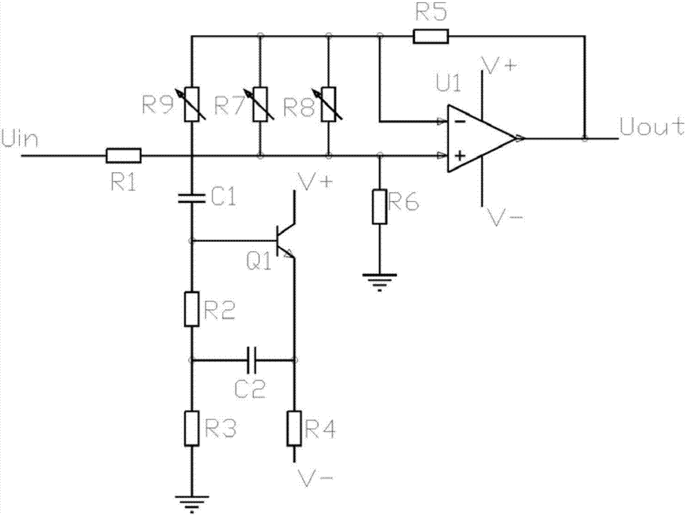
[0030] Such as image 3 As shown, the circuit includes operational amplifier U1, transistor Q1, capacitors C1 and C2, resistors R1~R6, and variable resistors R7~R9. The operational amplifier U1 is TL072. By adjusting the resistance of variable resistors R7~R9, The change of the system frequency f from 60Hz to 20KHz can be realized, which meets the range requirement of the selected speaker output frequency.
PUM
 Abstract
Description
Claims
Application Information
 - R&D
- Intellectual Property
- Life Sciences
- Materials
- Tech Scout
- Unparalleled Data Quality
- Higher Quality Content
- 60% Fewer Hallucinations
Browse by: Latest US Patents, China's latest patents, Technical Efficacy Thesaurus, Application Domain, Technology Topic, Popular Technical Reports.
© 2025 PatSnap. All rights reserved.Legal|Privacy policy|Modern Slavery Act Transparency Statement|Sitemap|About US| Contact US: help@patsnap.com


