
Mold-free casting forming device capable of automatically discharging sand

A technology of moldless casting and molding equipment, applied in the field of casting moldless casting, can solve the problems of complicated equipment, wear and tear of equipment transmission parts, poor practicability, etc., and achieve reasonable structure, convenient movement and braking, and strong practicability Effect

Inactive Publication Date: 2017-10-24
吴大江
View PDF1 Cites 7 Cited by
  • Summary
  • Abstract
  • Description
  • Claims
  • Application Information

AI Technical Summary

Problems solved by technology

[0002] The existing method of processing sand molds for non-pattern casting places the sand molds under the cutting knife, and the processing surface of the sand molds is set upwards. During the cutting process, the waste sand produced cannot be discharged naturally, resulting in the accumulation of waste sand between the knife and the knife. grinding tool
The solution in the prior art is to rely on manual cleaning or compressed air blowing and cleaning. Manual cleaning is time-consuming and laborious, which affects production efficiency; compressed air blowing and cleaning needs to increase the blowing device. The design cost and production cost of the blowing device, while increasing the energy and power consumption during production, finally increased the production cost of the moldless casting. The third is that the waste sand blown by the sand blasting device is flying, causing pollution to the working environment, and it is more likely Cause sand particles to enter the equipment transmission device, causing wear of equipment transmission parts and affecting the service life of equipment
[0003] For example, the patent application publication number CN 204621027 U discloses that it includes a numerical control cutting device, a sand box station control device, and a waste conveyor belt. The numerical control cutting device and the sand box station control device are fixed side by side on the ground, and the sand box station control device The installed sand box is placed at the processing position of the CNC cutting device, and the waste conveyor belt is installed between the CNC cutting device and the sand box station control device, below the sand mold processing station, but the device has a simple structure and poor practicability. Not suitable for promotional use

Method used


Image

  • Mold-free casting forming device capable of automatically discharging sand
  • Mold-free casting forming device capable of automatically discharging sand
  • Mold-free casting forming device capable of automatically discharging sand

Examples


Embodiment Construction

[0018] The following will clearly and completely describe the technical solutions in the embodiments of the present invention with reference to the accompanying drawings in the embodiments of the present invention. Obviously, the described embodiments are only some, not all, embodiments of the present invention. Based on the embodiments of the present invention, all other embodiments obtained by persons of ordinary skill in the art without making creative efforts belong to the protection scope of the present invention.

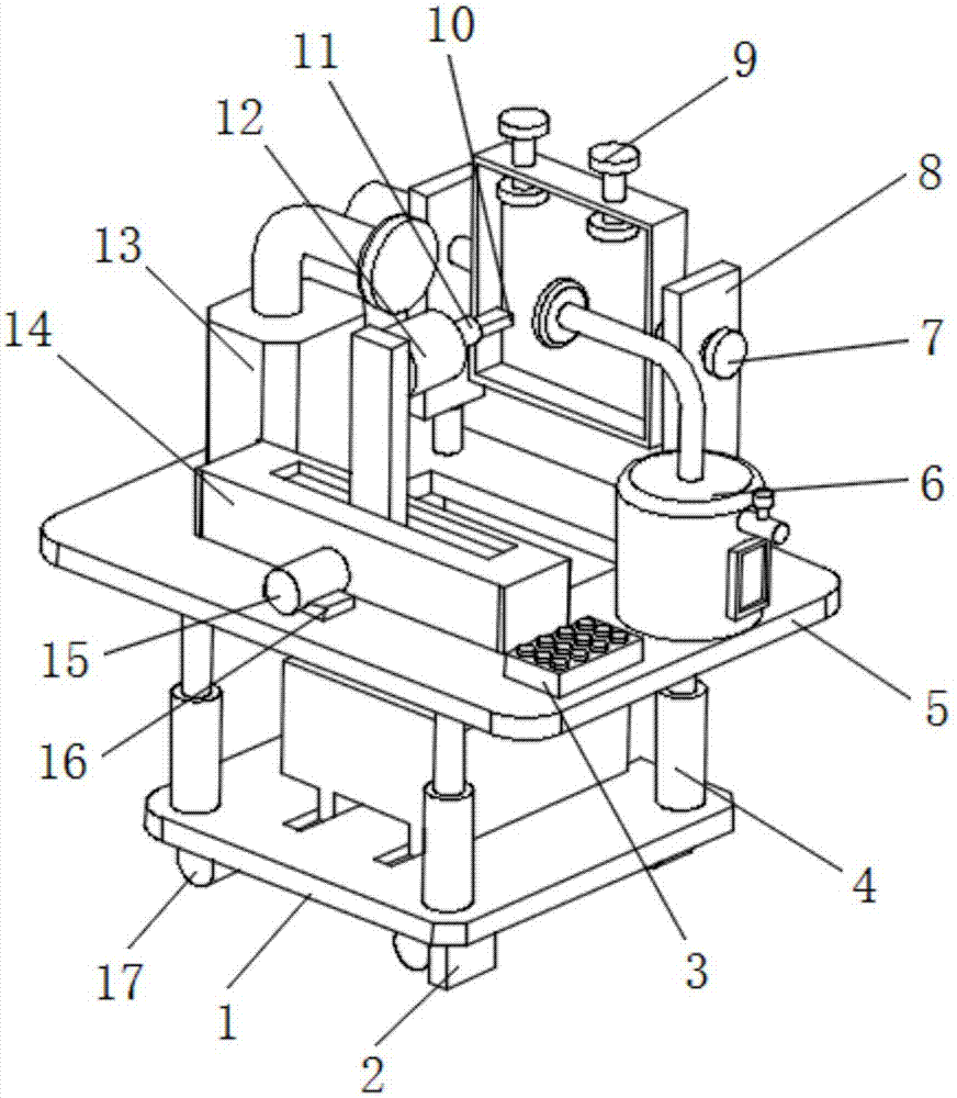
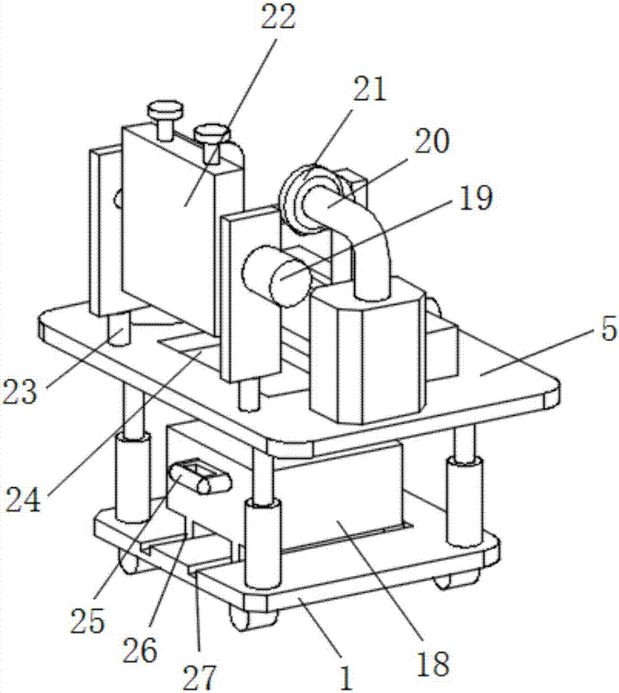
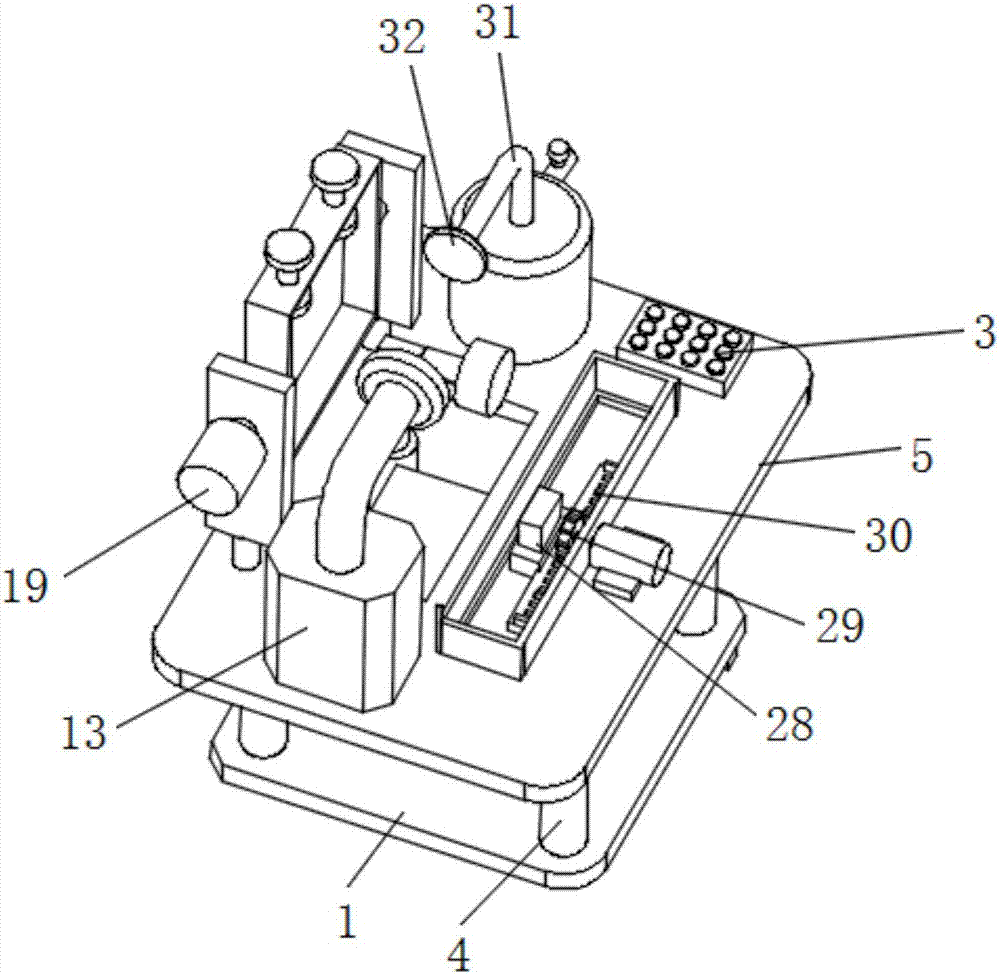
[0019] see Figure 1-3 , the present invention provides a technical solution: a moldless casting molding equipment that can automatically discharge sand, including a bottom plate 1, and four electric telescopic rods-4 are arranged on the upper surface of the bottom plate 1, and the work can be adjusted through the electric telescopic rods-4. The height of the table 5, the top of the electric telescopic rod 14 is provided with a workbench 5, and the position of...


PUM


Abstract

The invention discloses a moldless casting molding equipment capable of automatic sand discharge, which comprises a bottom plate, four electric telescopic rods 1 are arranged on the upper surface of the bottom plate, and a workbench is arranged on the top of the electric telescopic rod 1 . Two fixing plates are arranged on the upper surface of the workbench close to the rear side, and a through hole is arranged on the side of the fixing plate close to the upper surface. There are three servo motors. The moldless casting molding equipment that can automatically discharge sand has a reasonable structure and strong practicability. The dust floating during work can be cleaned and removed through the atomizer and vacuum cleaner, and the sand discharge tank and waste box The waste sand generated during work can be collected and processed to ensure a clean and hygienic working environment. The height of the workbench can be easily adjusted through the electric telescopic rod, and the device can be moved and braked through universal wheels and brakes. It is suitable for Promotional use.

Description

technical field [0001] The invention relates to the technical field of casting modeling without pattern casting, in particular to a patternless casting molding equipment capable of automatic sand discharge. Background technique [0002] The existing method of processing sand molds for non-pattern casting places the sand molds under the cutting knife, and the processing surface of the sand molds is set upwards. During the cutting process, the waste sand produced cannot be discharged naturally, resulting in the accumulation of waste sand between the knife and the knife. Grind knives. The solution in the prior art is to rely on manual cleaning or compressed air blowing and cleaning. Manual cleaning is time-consuming and laborious, which affects production efficiency; compressed air blowing and cleaning needs to increase the blowing device. The design cost and production cost of the blowing device, while increasing the energy and power consumption during production, finally inc...

Claims


Application Information

Patent Timeline
IPC IPC(8): B22C9/02B22D45/00
CPCB22C9/02B22D45/005
Inventor 吴大江
Owner 吴大江
Learn More