
Heating device of new energy passenger car

A warm air device and new energy technology, applied in vehicle parts, transportation and packaging, heating/cooling equipment, etc., can solve the problems of easy pollution of the environment, insufficient comfort, low efficiency, etc., and achieve uniform temperature, comfort and safety Good performance and simple structure

Pending Publication Date: 2017-10-24
SONGZ AUTOMOBILE AIR CONDITIONING
View PDF8 Cites 7 Cited by
  • Summary
  • Abstract
  • Description
  • Claims
  • Application Information

AI Technical Summary

Problems solved by technology

This heating method requires fuel oil, which is not efficient and is easy to pollute the environment. Sometimes it will cause the smell of fuel in the compartment, and the ride comfort is not enough.

Method used


Image

  • Heating device of new energy passenger car
  • Heating device of new energy passenger car

Examples


Embodiment 1

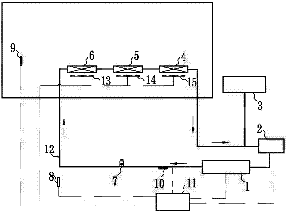
[0042] see figure 1 . The invention relates to a connection structure of water heating series for a heater device of a new energy bus, which includes a PTC liquid heater 1, a water pump 2, an expansion water tank 3, a first heater core 4, a second heater core 5, a third heater Air core 6, exhaust valve 7, first temperature sensor 8, second temperature sensor 9, third temperature sensor 10, controller 11, pipeline 12, first warm air blower 13, second warm air blower 14 and The third heater blower 15. The warm air device is a closed circulation system, which uses antifreeze and antirust liquid with certain insulation capacity as the circulating fluid, and the circulation is realized under the power of the water pump 2 .

[0043] Connect the inlet end of the PTC liquid heater 1 to the water outlet of the water pump 2 through the pipeline 12, and connect the water inlet (also the water return port) of the water pump 2 to the expansion tank 3 and the first heater through the pipe...

Embodiment 2

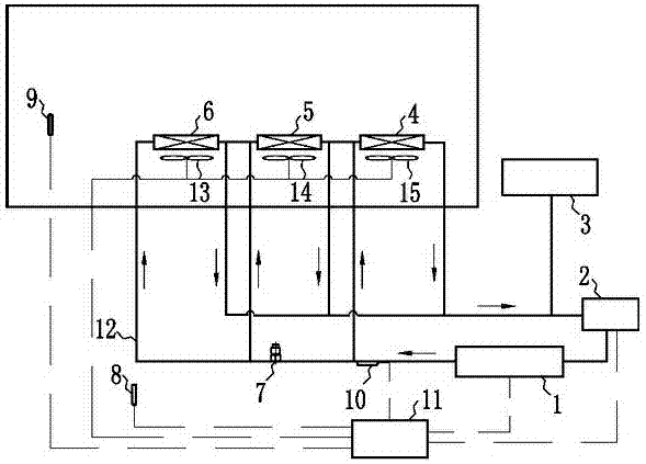
[0048] see figure 2 . The invention relates to a water heating parallel connection structure for a heater device of a new energy bus, comprising a PTC liquid heater 1, a water pump 2, an expansion water tank 3, a first heater core 4, a second heater core 5, a third heater Air core 6, exhaust valve 7, first temperature sensor 8, second temperature sensor 9, third temperature sensor 10, controller 11, pipeline 12, first warm air blower 13, second warm air blower 14 and The third heater blower 15. The warm air device is a closed circulation system, which uses antifreeze and antirust liquid with certain insulation capacity as the circulating fluid, and the circulation is realized under the power of the water pump 2 .

[0049] Connect the inlet end of the PTC liquid heater 1 to the water outlet of the water pump 2 through the pipeline 12, and connect the water inlet (also the water return port) of the water pump 2 to the expansion tank 3 and the first heater through the pipeline...


PUM


Abstract

The invention discloses a heating device of a new energy passenger car. The heating device is a closed circular system. Anti-freezing rust-proof liquid is used as the circular liquid for realizing circulation under the water pump power. The inlet end of PTC liquid heater is connected with a water outlet of a water pump by a pipeline. A water inlet of the water pump is connected with the outlet of a heating chip body and an expansion water tank. The outlet end of the PTC liquid heater is connected with the inlet end of the heating chip body by the pipeline. The pipeline of the outlet end of the PTC liquid heater is provided with an exhaust valve. One side of the heating chip body is provided with a heating fan. The exterior of a carriage, the interior of the carriage and the pipeline are provided with temperature sensors. The PTC liquid heater, the water pump, three temperature sensors and the heating fan are controlled by a controller. The heating device of the new energy passenger car is capable of solving the heating problem of the new energy passenger car under the low-temperature environment. Compared with the common air-conditioner, the air PTC heating is more comfortable, safe and energy-saving, and the cruising ability and service life of the new energy passenger car are indirectly increased.

Description

technical field [0001] The invention relates to the technical field of design and manufacture of automobile air conditioners, in particular to a new energy passenger car heater. Background technique [0002] Today's passenger cars are generally equipped with air conditioning. However, the on-board air conditioners of conventional passenger cars (such as air-conditioned buses) generally do not have a heating function, so a warm air core is installed under the seat of the passenger car, and the warm air core is connected to the engine cooling system. The coolant circulates to heat the cabin. [0003] In recent years, new energy vehicles with the advantages of low pollution and low noise have developed by leaps and bounds. However, the power source of the new energy bus is mainly the battery, so it cannot heat the cabin through the engine coolant circulation like a conventional bus. In late autumn and winter in northern my country, the temperature is often very low, and new ...

Claims


Application Information

Patent Timeline
IPC IPC(8): B60H1/22B60H1/00
CPCB60H1/00385B60H1/2221B60H2001/2228Y02T10/88
Inventor 孟彦邢艳青张逵刘运科赵凯
Owner SONGZ AUTOMOBILE AIR CONDITIONING
Learn More