Coding beam-splitting phase measurement device and method

A technology of phase measurement and beam splitting, which is applied in measurement devices, measurement optics, optical radiation measurement, etc., can solve problems such as low measurement resolution, limited number of Hartmann sensor array units, and high price of interferometers. High signal-to-noise ratio, simple structure and data recording process, and high-resolution effects

Active Publication Date: 2017-10-27
SHANGHAI INST OF OPTICS & FINE MECHANICS CHINESE ACAD OF SCI
View PDF3 Cites 14 Cited by
  • Summary
  • Abstract
  • Description
  • Claims
  • Application Information

AI Technical Summary

Problems solved by technology

Interferometry requires a large optical platform with a high degree of vibration isolation and a regular reference light, which requires extremely high environmental stability, and the interferometer is expensive; Hartmann sensors are widely used in phase measurement, but due to the Hartmann sensor array Limited number of units and poor measurement resolution

Method used


Image

  • Coding beam-splitting phase measurement device and method
  • Coding beam-splitting phase measurement device and method
  • Coding beam-splitting phase measurement device and method

Examples


Embodiment Construction

[0039] The present invention will be further described below in conjunction with the embodiments and accompanying drawings, but the protection scope of the present invention should not be limited thereby.

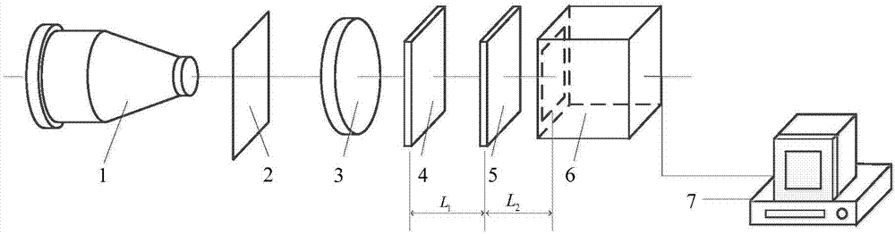
[0040] see first figure 1 , figure 1It is a schematic diagram of the encoding beam splitting phase measuring device of the present invention. It can be seen from the figure that a coded beam-splitting phase measurement device of the present invention includes: a beam reducer 1, an incident plane 2, a lens 3, and a diffraction grating 4 with known order distribution along the propagation direction of the incident light of the beam to be measured. , distribution known diffraction sample 5, spot detector 6 and computer 7, described incident plane 2 is positioned at described lens 3 front 2 times of focal length place, the target surface of described spot detector 5 and described The distance of the lens 3 is 2 times the focal length, the diffraction grating 4 is placed betwe...


PUM


Abstract

The invention discloses a coding beam-splitting phase measurement device and method, and the device just needs one light spot detector, one weak scattering sample in the known distribution, two-dimensional gratings with the equal diffraction-order light intensity distribution, and a corresponding fixing device. The cost of the device is far less than the cost of a conventional interferometer, and the device exerts low requirements for the stability of an environment. A to-be-measured light beam is split by the gratings, and then forms a plurality of separated diffraction spots on an imaging target surface through the weak scattering sample in the known distribution. An iteration algorithm is used for processing each diffraction spot, and the wavefront amplitude and phase of the to-be-measured light beam are restored. According to the invention, the plurality of different diffraction spots are obtained through the splitting effect of the gratings. Compared with a method employing one diffraction spot for iteration restoration, the method is higher in resolution in an iteration restoration process. Because only one diffraction spot needs to be recorded, the measurement process is simple and quick. The device and method can be used for the wavefront detection of pulse laser, and provide a solution for the wavefront measurement.

Description

technical field [0001] The invention relates to wavefront phase detection, in particular to a coding beam splitting phase measuring device and a measuring method. technical background [0002] Wavefront phase detection has an important application in high-power laser drivers. Due to the large size and complex internal structure of high-power laser devices, the quality of the laser beam will inevitably be affected during the processing and installation of optical components, causing the wavefront of the laser beam to occur. Distortion, reduced spot uniformity, and focal spot deformation affect the success rate of high-power laser experiments. Therefore, real-time detection of wavefront phase distortion in high-power laser drivers is of great significance for correcting beam wavefront distortion and improving beam quality. [0003] At present, the main methods of wavefront phase detection include interferometer, shear interferometer, Hartmann sensor and so on. Interferometry ...

Claims


Application Information

Patent Timeline
Patent Type & Authority Applications(China)
IPC IPC(8): G01J9/00
CPCG01J9/00G01J2009/002
Inventor 刘诚何西潘兴臣陶华朱健强
Owner SHANGHAI INST OF OPTICS & FINE MECHANICS CHINESE ACAD OF SCI
Why Eureka
Try Eureka