Method for analyzing an object and charged particle beam device for carrying out the method

A technology of charged particle beams and charged particles, applied to circuits, discharge tubes, electrical components, etc., can solve problems such as incomprehensible information and errors

Active Publication Date: 2017-10-27
CARL ZEISS MICROSCOPY GMBH +1
View PDF4 Cites 2 Cited by
  • Summary
  • Abstract
  • Description
  • Claims
  • Application Information

AI Technical Summary

Problems solved by technology

Therefore, information provided by EDX spectra may not be interpreted or may lead to erroneous results

Method used


Image

  • Method for analyzing an object and charged particle beam device for carrying out the method
  • Method for analyzing an object and charged particle beam device for carrying out the method
  • Method for analyzing an object and charged particle beam device for carrying out the method

Examples


Embodiment Construction

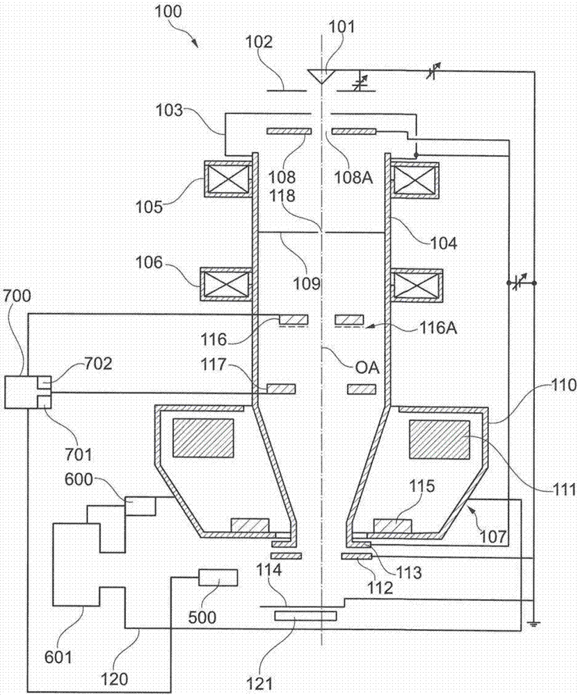
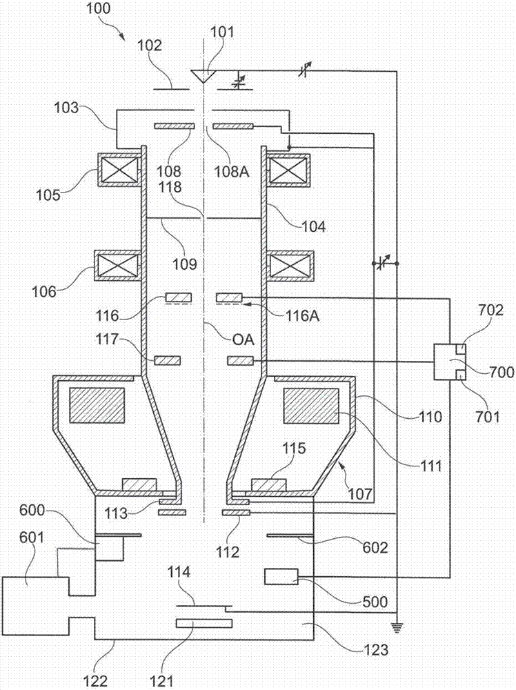
[0071] figure 1 A schematic diagram of the SEM 100 is shown. The SEM 100 has a beam generator in the form of an electron source 101 as cathode, an extraction electrode 102 and an anode 103 which is arranged at one end of a beam guide tube 104 of the SEM 100 . The electron source 101 is, for example, a thermal field emitter. However, the present invention is not limited to such an electron source. Rather, any electron source can be used.

[0072] Electrons emitted from the electron source 101 form a primary electron beam. Electrons are accelerated to the anode potential due to the potential difference between the electron source 101 and the anode 103. The anode potential in this exemplary embodiment is between 0.2 kV and 30 kV relative to the ground potential of the object chamber 120, for example 5 kV to 15 kV, specifically 8 kV, but it could alternatively be ground potential.

[0073] Two condensing lenses are arranged at the beam guiding tube 104, that is, the first con...


PUM


Abstract

The system described herein relates to analyzing an object using a charged particle beam device generating a beam of charged particles and to the charged particle beam device for analyzing the object. A part of an image of the object corresponding to a volume unit surface of a volume unit is segmented into an area having a first color level and a second color level as well corresponding area fractions are determined. A plurality of particles with color levels are identified by comparing the color levels with the information stored in a database. By comparing the color levels, it is possible to identify the potential particles, for example minerals, which may be included in the volume unit.

Description

technical field [0001] The invention relates to a method for analyzing an object using a charged particle beam device generating a charged particle beam. Furthermore, the invention relates to a charged particle beam device for carrying out such a method. In particular, the charged particle beam device is an electron beam device and / or an ion beam device. Background technique [0002] Charged particle beam devices are used to analyze and examine objects (hereinafter also referred to as samples) in order to gain insight into the properties and behavior of the object under specific conditions. One of these charged particle beam devices is an electron beam device, in particular a scanning electron microscope (also called SEM). [0003] In the SEM, an electron beam (hereinafter also referred to as primary electron beam) is generated using a beam generator. The electrons of the primary electron beam are accelerated to a predetermined energy and focused onto the sample to be ana...

Claims


Application Information

Patent Timeline
Patent Type & Authority Applications(China)
IPC IPC(8): H01J37/28H01J37/244
CPCH01J37/244H01J37/28H01J37/222H01J2237/24578H01J2237/24585H01J2237/2803H01J2237/2813H01J37/261
Inventor S.巴蒂普罗鲁E.希尔
Owner CARL ZEISS MICROSCOPY GMBH
Why Eureka
Try Eureka