USB3.0 optical fiber expansion card based on PCI-E

A USB2.0, PCI-E technology, applied in optical fiber transmission, instruments, electrical digital data processing, etc., can solve problems such as electromagnetic interference, data security cannot be guaranteed, and USB3.0 standard terminal equipment cannot be connected.

Pending Publication Date: 2017-10-27
广东启鼎光电科技有限公司
View PDF0 Cites 7 Cited by
  • Summary
  • Abstract
  • Description
  • Claims
  • Application Information

AI Technical Summary

Problems solved by technology

Since the transmission rate has been increased from 480Mbps specified in the previous USB2.0 standard to 5Gbps, the use of traditional cables generally does not exceed 3 meters. After some manufacturers use relay amplifier chips, the transmission distance can only reach a maximum of 15 meters. Transmission distance, but because cable transmission is particularly susceptible to electromagnetic interference during use, it is not suitable for use on some industrial production lines with large electromagnetic interference, and some equipment sensitive to electromagnetic interference (such as military equipment) Currently, with the rise of Industry 4.0, the transmission distance of many USB3.0 industrial cameras will exceed this distance, and even reach a distance of several hundred meters. Management, users can only use USB3.0 storage devices and USB3.0 printers at the remote end, so as to realize the safe isolation between the computer host and the user, and the distance between the computer and the terminal often reaches hundreds of meters, and the data is in the process of transmission There must be no electromagnetic leakage in the system, which will cause the data security not to be guaranteed
However, we use optical fiber to transmit USB3.0 signals to solve the problem of electromagnetic interference and the problem of transmission distance. In addition, although there are some devices that can realize long-distance transmission of USB3.0 signals, they generally use terminal equipment The USB3.0 data is parsed into other data formats by the USB3.0 physical layer chip and then re-encoded and converted into optical fiber for transmission. The other end converts the received optical signal into an electrical signal, which is converted into a parallel signal by the USB3.0 physical layer chip The data is sent to the acquisition card for data acquisition. They are all aimed at some specific equipment applications and cannot realize the access of other USB3.0 standard terminal equipment. For example, a device used to realize USB3.0 industrial camera long-distance transmission cannot It is used to access other USB3.0 terminal devices such as U disk, USB3.0 mobile hard disk or printer, and there is no solution that can directly convert the PCI-E interface into a USB3.0 optical fiber interface.

Method used


Image

  • USB3.0 optical fiber expansion card based on PCI-E
  • USB3.0 optical fiber expansion card based on PCI-E
  • USB3.0 optical fiber expansion card based on PCI-E

Examples


Embodiment Construction

[0064] In order to better understand the present invention, the present invention will be further described below in conjunction with the accompanying drawings and embodiments. It should be understood that the specific embodiments described here are only used to explain the present invention, but not to limit the present invention. In addition, it should be noted that, for the convenience of description, only some parts related to the present invention are shown in the drawings but not all circuit structures.

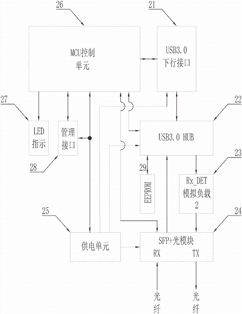
[0065] The present invention is a PCI-E-based USB3.0 optical fiber expansion card and USB3.0 optical fiber receiving end; the system application principle block diagram is as follows figure 1 As shown, one end of the USB3.0 fiber optic expansion card S2 is connected to the PCI-E bus S1 of the host computer, and the other end is connected to the USB3.0 optical fiber receiving end S3 through an optical fiber; the downlink interface of the USB3.0 optical fiber receiving e...


PUM


Abstract

The invention discloses a USB3.0 optical fiber expansion card based on PCI-E. A plurality of USB3.0 interfaces can be converted through a PCI-E technology, and the USB3.0 electric signal of the USB3.0 interfaces is converted into an optical signal for transmission by adopting an optical fiber; the USB3.0 optical fiber expansion card is cooperatively used together with a USB3.0 optical fiber receiving end; a USB2.0 boost engine is contained inside a USB3.0 HUB main control chip at the USB3.0 optical fiber receiving end; therefore, USB2.0 data and USB3.0 data can be transmitted simultaneously through USB3.0 ultra high-speed signals by using an optical fiber, four ports of the USB3.0 HUB main control chip can be connected with USB2.0 or USB3.0 terminal periphery equipment, and all terminal equipment according with the USB3.0/2.0/1.1/1.0 standard can be normally connected.

Description

technical field [0001] The invention relates to the field of communication between USB3.0 and PCI Express, in particular to a PCI-E conversion USB3.0 optical fiber interface, specifically a PCI-E-based USB3.0 optical fiber expansion card. [0002] The invention also relates to an automatic negotiation method for optical fiber communication between the USB3.0 optical fiber expansion card and the USB3.0 optical fiber receiving end. [0003] The invention also relates to a method for digitally diagnosing the USB3.0 optical fiber expansion card and the USB3.0 optical fiber receiving end and remotely controlling the USB3.0 terminal equipment. Background technique [0004] The basic technology of PCI Express 2.0 follows the technology of the previous generation version 1.0, which adopts high-speed serial bus technology and relies on high frequency to obtain high performance. Therefore, PCI Express was once called "serial PCI". Due to the strong anti-interference ability of serial...

Claims


Application Information

Patent Timeline
Patent Type & Authority Applications(China)
IPC IPC(8): H04B10/25G06F13/38
CPCG06F13/385G06F2213/0026G06F2213/0042G06F2213/3852H04B10/2589H04B10/25891
Inventor 胡承恩
Owner 广东启鼎光电科技有限公司
Why Eureka
Try Eureka