Turbine impeller

A turbine impeller and turbine technology, which is applied to gas turbine devices, blade support elements, non-variable-capacity pumps, etc., can solve the problems of poor energy conversion efficiency and difficulty in ensuring the angle of attack, and achieve high energy conversion efficiency.

Inactive Publication Date: 2017-10-31
HONDA MOTOR CO LTD
View PDF5 Cites 1 Cited by
  • Summary
  • Abstract
  • Description
  • Claims
  • Application Information

AI Technical Summary

Problems solved by technology

[0007] However, the shape of the tip of the blade of the conventional turbine impeller has the following problems: it is difficult to ensure an appropriate angle of attack when the inflow speed of the exhaust gas changes to a medium speed or a low speed, and the energy conversion efficiency is poor.

Method used


Image

  • Turbine impeller
  • Turbine impeller
  • Turbine impeller

Examples


Embodiment Construction

[0041] Hereinafter, an embodiment of the present invention will be described in detail with reference to the drawings.

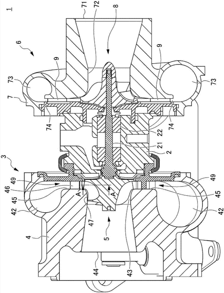
[0042] figure 1 It is a sectional view showing a supercharger 1 according to an embodiment.

[0043] A supercharger 1 according to the present invention includes a bearing housing 2 , a turbine 3 mounted on one end side of the bearing housing 2 , and a compressor 6 mounted on the other end side of the bearing housing 2 .

[0044] The bearing body 2 includes: a rod-shaped rotating shaft 21 extending between the turbine 3 and the compressor 6 ; and a bearing 22 rotatably supporting the rotating shaft 21 .

[0045] The compressor 6 includes a compressor housing 7 constituting a part of an intake passage of the internal combustion engine, a compressor impeller 8 and a diffuser 9 provided in the compressor housing 7 .

[0046] In the compressor housing 7, an annular compressor wheel chamber 72, an annular scroll flow path 73, and an annular intake flow path 74 ...


PUM


Abstract

A turbine impeller supplies a high-pressure fluid through a scroll flow route and / or a exhaust supply port of a fixed nozzle and includes: blade components converting the fluid into a rotational force; and a rotor, configured with the blade components and can rotate around a specified rotational axis, wherein a direction, relative to a gas relative inflow velocity of the rotor, specified by using the fluid supply port as a starting point and subtracting a rotational velocity component of the rotor from a supply velocity component of the fluid is set to not intersect with the rotational axis of the rotor; and a shape, from a halfway portion to a front edge portion, of the blade component inclines, relative to a direction from a center of the rotor to an upstream portion of the blade component, toward front side of a rotating direction of the rotor by a specified angle.

Description

technical field [0001] The present invention relates to a turbine impeller. Background technique [0002] Conventionally, as a turbine impeller installed in a flow path of an internal combustion engine (hereinafter referred to as an engine), there is known a turbine impeller in which the shape of the tip of the blade of the turbine impeller is oriented toward the gas relative inflow velocity of the following velocity triangle: The inflow direction of V is formed so that the velocity triangle is formed by the inflow velocity C of the exhaust gas flowing into the rotor blade inlet, the rotational velocity U in the circumferential direction of the rotor blade, and the relative gas inflow velocity V (for example, refer to Patent Document 1). . [0003] [Prior art literature] [0004] [Patent Document] [0005] [Patent Document 1] Japanese Patent Laid-Open No. 2011-132810 Contents of the invention [0006] [Problem to be solved by the invention] [0007] However, the shape...

Claims


Application Information

Patent Timeline
Patent Type & Authority Applications(China)
IPC IPC(8): F01D1/22F01D5/14
CPCF01D1/22F01D5/141F01D5/048F02C6/12F04D25/024F05D2220/40F01D5/147F04D25/04
Inventor 久野直树伊藤直纪
Owner HONDA MOTOR CO LTD
Why Eureka
Try Eureka