Intelligent optical guiding system

A technology of optical guidance and guidance devices, applied in control/regulation systems, non-electric variable control, instruments, etc., can solve problems such as misjudgment, easy wear and tear of marking lines, and misidentification, so as to reduce reconstruction and reduce path laying , The effect of facilitating follow-up equipment maintenance

Pending Publication Date: 2017-10-31
王锦海
View PDF2 Cites 13 Cited by
  • Summary
  • Abstract
  • Description
  • Claims
  • Application Information

AI Technical Summary

Problems solved by technology

The guidance method is that the image processing algorithm is relatively complicated, and the marking lines laid on the ground are easy to wear and cause misidentification
6) Reflective laser guidance method, in which the laser scanning radar is installed on the trolley to scan the laser reflection plate installed at the precise position around the driving path. Laser beams are used to determine its current location and navigate. This guidance method requires a series of reflectors to be pre-set around the path to be driven, and the cost is relatively high.
[0005] Aiming at the guidance scheme of AGV trolley, patent CN1263625C proposes an optically guided automatic guided vehicle guidance device. This patent combines the above-mentioned methods 4 and 6, and the laser emitting board needs to be erected in advance. Patent CN103019240B proposes to use ultrasonic sensors to sense Measure the distance information around the preset path and pre-store it in the database to provide path correction information for the subsequent trolley travel. Although this method does not set up auxiliary equipment on the predetermined path, it can target objects that suddenly appear in the path, such as people walking, etc. lead to wrong judgment

Method used


Image

  • Intelligent optical guiding system
  • Intelligent optical guiding system
  • Intelligent optical guiding system

Examples


Embodiment Construction

[0034] The present invention will be described in further detail below in conjunction with the accompanying drawings and preferred embodiments.

[0035] The intelligent optical guidance system proposed by the present invention is mainly used in the field of guiding the running path of unmanned sports cars and moving robots, and especially relates to the automatic guiding system of the running path of storage and handling robots.

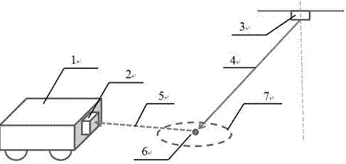
[0036] figure 1 A schematic diagram of an intelligent optical guidance system provided by the present invention is shown. 1 is the guided car or robot, 2 is the reflected light point detection unit, 3 is the guiding light source placed on the motion electronic control platform, 4 is the guiding light beam, 5 is the reflected light beam, and 6 is the light source for the guiding light beam to irradiate the ground. The light spot 7 is the detection area of ​​the light spot detection unit. When the light point detection unit detects the light point of t...


PUM


Abstract

The present invention discloses an optical guiding device and method. The device includes a guided device 1, an optical detection unit 2 and a guiding light source 3. Depending on the actual use situation, an indicating light source or a video display module can also be added. The invention can solve the problems of automatic navigation of storage AGV trolleys, robot walking path navigation, toy car navigation and the like. Compared with conventional RFID wireless navigation, the present invention adopts methods such as laying magnetic materials on the ground, laser active scanning navigation, etc., and adopts low-cost, small-volume guiding light sources to realize automatic guiding functions, eliminating the need to do a lot of work on designing track routes on the ground, fully Taking advantage of the space advantage, the running trajectory can be flexibly changed according to the needs, which is easier to promote vigorously than other automatic navigation methods.

Description

technical field [0001] The invention relates to the field of unmanned moving trolleys and moving path guidance for moving robots, in particular to an automatic guiding system for the running paths of storage and handling robots. Background technique [0002] With the rapid development of society, a large number of goods have been introduced to the market one after another. Whether it is the warehouse management of large companies or the logistics and warehousing of e-commerce platforms, they all face the problem of goods in and out of the warehouse. Handling robots (AGV, Automated Guided Vehicle for short) are widely used in industry, transportation, warehouse management and other fields. The existing handling robots on the market are equipped with automatic guidance devices such as electromagnetic or optical, which can drive along the prescribed guidance path. [0003] At present, there are mainly the following methods for AGV guidance technology, and these methods have mor...

Claims


Application Information

Patent Timeline
Patent Type & Authority Applications(China)
IPC IPC(8): G05D1/02
CPCG05D1/0234G05D1/0236G05D1/0242
Inventor 不公告发明人
Owner 王锦海
Why Eureka
Try Eureka