Device and method for manufacturing PDMS surface patterning puckers based on laser

A surface pattern and wrinkle technology, which is applied in the field of laser-based PDMS surface patterned wrinkle devices, can solve the problems of poor controllability and complicated process, and achieve the effects of fast patterning, simple process, and easy operability

Active Publication Date: 2017-11-03
GUANGDONG UNIV OF TECH
View PDF5 Cites 1 Cited by
  • Summary
  • Abstract
  • Description
  • Claims
  • Application Information

AI Technical Summary

Problems solved by technology

[0009] Whether it is mechanical stretching method, heating induction method or solvent swelling induction method, a hard layer must first be prepared on the surface of PDMS, and the method of preparing the hard layer is It is mainly based on chemical reaction or evaporation, and because the prepared wrinkles are in the micro-nano scale, it has obvious disadvantages such as complex process, poor controllability, and limited to large-area preparation. When small-area patterning is required to prepare the wrinkle structure , it is necessary to add a mask plate, so a certain accuracy requirement is made for the pattern accuracy of the mask plate

Method used


Image

  • Device and method for manufacturing PDMS surface patterning puckers based on laser
  • Device and method for manufacturing PDMS surface patterning puckers based on laser
  • Device and method for manufacturing PDMS surface patterning puckers based on laser

Examples


Embodiment Construction

[0030] The following will clearly and completely describe the technical solutions in the embodiments of the present invention with reference to the accompanying drawings in the embodiments of the present invention. Obviously, the described embodiments are only part of the embodiments of the present invention, not all of them. Based on the embodiments of the present invention, all other embodiments obtained by persons of ordinary skill in the art without creative efforts fall within the protection scope of the present invention.

[0031] It should be noted that if there is a directional indication (such as up, down, left, right, front, back...) in the embodiment of the present invention, the directional indication is only used to explain the position in a certain posture (as shown in the accompanying drawing). If the specific posture changes, the directional indication will also change accordingly.

[0032] In addition, if there are descriptions involving "first", "second" and ...


PUM


Abstract

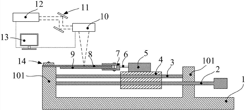
The invention discloses a device for manufacturing PDMS surface patterning puckers based on the laser. The device for manufacturing the PDMS surface patterning puckers based on the laser comprises a base. Two supporting blocks are arranged on the top face of the base, protrude upwards and are spaced for a certain distance. A lead screw and a moving platform are arranged on the base. The lead screw drives the moving platform to horizontally slide for cooperation. The side face of the moving platform is connected with a clamp through a connection rod. The clamp tightly clamps the same end of a PDMS plate and a metal plate which are vertically and tightly attached to each other. The PDMS plate is placed on the top face of the metal plate. The other end of the PDMS plate is fastened to the top end of the supporting block through a press plate. A scanning galvanometer is arranged above the PDMS plate and electrically connected with a computer server. The computer server is electrically connected with a laser device. The laser device emits laser beams, and the laser beams enter the input end of the scanning galvanometer. The scanning galvanometer enables focused laser beams to illuminate the surface of the PDMS plate downwards. The invention further provides a method for manufacturing the PDMS surface patterning puckers based on the laser. Compared with the prior art, the device and method or manufacturing the PDMS surface patterning puckers based on the laser have the advantages of being simple in technology, capable of achieving rapid, easy and convenient pattering, good in operability, scientific, environmentally friendly and the like.

Description

technical field [0001] The invention relates to the technical field of laser micro-nano manufacturing, in particular to a device and method for preparing PDMS surface patterned wrinkles based on laser. Background technique [0002] PDMS is called polydimethylsiloxane, which has good processability, biocompatibility, light transmittance, thermal stability, non-toxicity and elasticity, etc. It can not only be used to process conventional microfluidic chips , can also be used as the structural material of the space cell culture chip. However, the smooth and untreated PDMS surface has relatively large limitations in application, such as the inability of cells to directly adhere to the surface for production, poor survival rate, and random growth direction. [0003] Surface wrinkle technology has been applied in technical fields such as microfluidics, superhydrophobic surface, mechanical measurement of thin film materials, and directional growth of cells due to its advantages of...

Claims


Application Information

Patent Timeline
IPC IPC(8): B29C59/16B29L7/00
CPCB29C59/002B29C59/16B29L2007/001
Inventor 郭钟宁洪文生邓宇麦文豪张会寅
Owner GUANGDONG UNIV OF TECH
Why Eureka
Try Eureka