A flat plate resistance testing device for experiment

A test device, flat plate resistance technology, which is applied in the field of experimental flat plate resistance test device, can solve the problems of small measuring range, error, and affecting the accuracy of measurement results, etc., and achieve the effect of reducing measurement error and appropriate measuring range

Active Publication Date: 2019-11-05
HARBIN INST OF TECH AT WEIHAI
View PDF7 Cites 0 Cited by
  • Summary
  • Abstract
  • Description
  • Claims
  • Application Information

AI Technical Summary

Problems solved by technology

[0003] Due to the small value of the frictional resistance in the experiment, it is very difficult to accurately measure the frictional resistance of the flat plate. The main influencing factors are as follows: First, other resistance components are inevitable in the experiment, even if the values ​​of other resistance components A very small force will also cause a large error; second, the dynamometer required for the experiment must have a small range and high precision, and there are few dynamometers that can meet the aforementioned requirements in the prior art; third, the vibration of the test frame in the experiment , tilt and buoyancy will affect the accuracy of the measurement results

Method used


Image

  • A flat plate resistance testing device for experiment
  • A flat plate resistance testing device for experiment
  • A flat plate resistance testing device for experiment

Examples


Embodiment 1

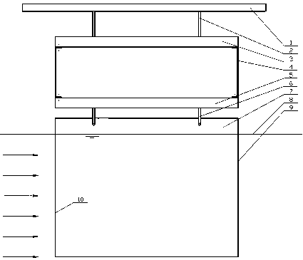
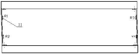
[0034] A test device for the resistance of an experimental flat plate, the test device comprising three parts of an experimental stand, a dynamometer and an experimental plate installed sequentially from top to bottom, the dynamometer, the experimental stand and the experimental plate are all connected by a hook; The width of the dynamometer is not less than the width of the experimental plate; the length of the experimental plate is a thin steel plate with a length of 1000 mm, a width of 700 mm, and a thickness of 4 mm to reduce wave resistance. The experimental flat plate is vertically hoisted on the lower end of the dynamometer in a two-point hoisting manner, so as to avoid the deformation of the experimental flat plate under the action of gravity and the occurrence of hydrodynamic excitation. The hoisting position is 25% away from the leading edge and the trailing edge of the experimental plate, that is, 50mm. The lower end of the experimental plate is immersed below the wat...

Embodiment 2

[0042] A test device for the resistance of an experimental flat plate, the test device includes three parts: an experimental stand, a dynamometer and an experimental plate installed from top to bottom. The dynamometer, the experimental stand and the experimental plate are all connected by a lifting ring; The width of the dynamometer is not less than the width of the experimental plate; the length of the experimental plate is a thin steel plate with a length of 2000 mm, a width of 1500 mm, and a thickness of 8 mm to reduce wave making resistance. The experimental plate is vertically hoisted on the lower end of the dynamometer in a two-point hoisting manner, so as to avoid the deformation of the experimental plate under the action of gravity and the occurrence of hydrodynamic excitation. The hoisting position is at a distance of 20% of the length of the pilot and follow-up test plates, that is, 400mm. The lower end of the test plate is immersed below the water surface; the leading...

Embodiment 3

[0044] A test device for the resistance of an experimental flat plate, the test device comprising three parts of an experimental stand, a dynamometer and an experimental plate installed sequentially from top to bottom, the dynamometer, the experimental stand and the experimental plate are all connected by a hook; The width of the dynamometer is not less than the width of the test plate; the test plate has a length of 500mm, a width of 300mm, and a thin steel plate with a thickness of 3mm to reduce wave resistance. The experimental plate is vertically hoisted at the lower end of the dynamometer in a two-point hoisting manner, so as to avoid the deformation of the experimental plate under the action of gravity and the occurrence of hydrodynamic excitation. The hoisting position is 15% away from the leading edge and the trailing edge of the experimental plate, which is 75mm. The lower end of the experimental plate is immersed below the water surface; the leading edge and trailing e...


PUM

PropertyMeasurementUnit
thicknessaaaaaaaaaa
lengthaaaaaaaaaa
widthaaaaaaaaaa

Abstract

The invention relates to a resistance test device of an experiment flat plate. The test device comprises an experiment support, a dynamometer and an experiment flat plate which are up-down successively installed. The dynamometer is flexibly connected with the experiment support and the experiment flat plate. The width of the dynamometer is not less than the width of the experiment flat plate. The experiment flat plate is vertically hoisted, and the lower end part is immersed under the water surface. The guidance edge of the experiment flat plate is wedge-shaped. The dynamometer consist of an upper rigid beam, a lower rigid beam, a stress sheet and two elastic steel sheets installed on two ends of the upper and lower rigid beams. The elastic steel sheets are fastened on two ends of the upper and lower rigid beams through bolts. Stress sheets are arranged on the elastic steel sheets and are connected in a full bridge manner. According to the invention, adhesion resistance caused by the thickness of the test device and wave making resistance caused by the existence of the test device on the water surface are reduced; appendage resistance is avoided; and the elastic steel sheets can be replaced according to actual demands, so the proper range is ensured.

Description

Technical field [0001] The invention relates to an experimental flat resistance test device, in particular to a test device capable of accurately measuring the friction resistance of flat plates with different roughness and different coatings in water. Background technique [0002] In the field of rapid design of the hull, accurate testing of the frictional resistance of the flat plate in the water is the basis for calculating the frictional resistance of the hull surface. In the experimental measurement, the plate should be placed in still water to move at a determined speed, or the plate should be placed in a water tank with a uniform, stable and definite flow rate, and the total resistance of the plate at this time should be measured. In the experiment, ensure that the direction of the water flow velocity is parallel to the plate. In the actual measured total resistance, the frictional resistance is only a part of it, and it also includes other resistance components, such as ...

Claims


Application Information

Patent Timeline
Patent Type & Authority Patents(China)
IPC IPC(8): G01L1/04
CPCG01L1/04
Inventor 周军伟梅蕾
Owner HARBIN INST OF TECH AT WEIHAI
Why Eureka
Try Eureka