Permanent magnetic coupling adjustable-speed motor

A speed-regulating motor, permanent magnet coupling technology, applied in the direction of permanent magnet clutch/brake, magnetic circuit, electromechanical device, etc., can solve the problems of high installation environment requirements, high cost, difficult maintenance and repair, etc., and achieve a large speed regulation range. , the effect of smooth speed regulation and hard characteristics

Pending Publication Date: 2017-11-03
JIANGSU MAGNET VALLEY TECH
View PDF3 Cites 3 Cited by
  • Summary
  • Abstract
  • Description
  • Claims
  • Application Information

AI Technical Summary

Problems solved by technology

However, the frequency converter, the key device of frequency control, has large capacity, complex technology, high cost, high requirements for installation environment, and difficult maintenance and repair.

Method used


Image

  • Permanent magnetic coupling adjustable-speed motor
  • Permanent magnetic coupling adjustable-speed motor
  • Permanent magnetic coupling adjustable-speed motor

Examples


Embodiment 1

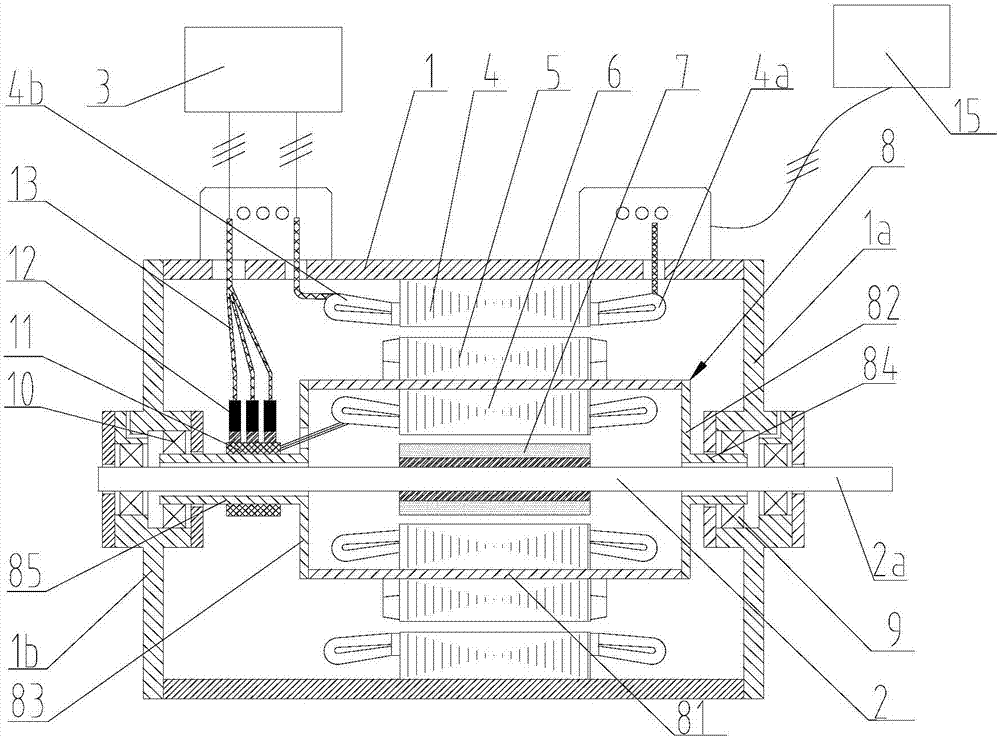
[0065] Such as figure 1 As shown, Embodiment 1 of the present invention provides a permanent magnet coupling speed regulating motor, which includes: a housing 1, an output shaft 2, a control structure 3, an electric structure, and a speed regulating structure; wherein, the electric The structure is composed of an electric rotor 5 and a stator 4 arranged on the inner wall of the casing 1. The speed regulating structure includes a winding rotor 6 and a permanent magnet rotor 7; the magnetic field of the stator 4 interacts with the magnetic field of the electric rotor 5 to transmit torque, and the winding rotor 6 The magnetic field of the permanent magnet rotor 7 interacts with the magnetic field to transmit torque; the winding rotor 6 is fixedly connected with the electric rotor 5, the permanent magnet rotor 7 is fixedly connected with the output shaft 2, the permanent magnet rotor 7, the winding rotor 6, the electric rotor 5 and The stator 4 is sequentially arranged along the r...

Embodiment 2

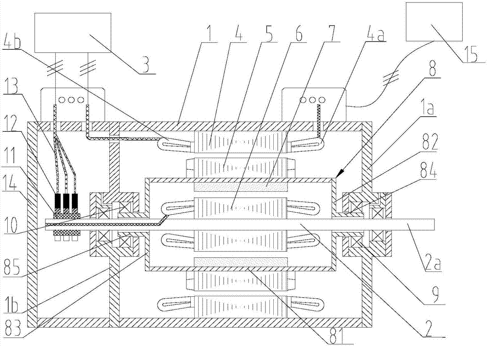
[0099] Such as figure 2 As shown, the permanent magnet coupling speed regulating motor provided by Embodiment 2 of the present invention includes: a casing 1, an output shaft 2, a control structure 3, an electric structure, and a speed regulating structure; wherein, the electric structure consists of The electric rotor 5 is composed of a stator 4 arranged on the inner wall of the housing 1, and the speed regulating structure includes a winding rotor 6 and a permanent magnet rotor 7; the magnetic field of the stator 4 interacts with the magnetic field of the electric rotor 5 to transmit torque, and the magnetic field of the winding rotor 6 Interact with the magnetic field of the permanent magnet rotor 7 to transmit torque; the permanent magnet rotor 7 is fixedly connected with the electric rotor 5, the winding rotor 6 is fixedly connected with the output shaft 2, the winding rotor 6, the permanent magnet rotor 7, the electric rotor 5 and the stator 4 Arranged sequentially alon...

Embodiment 3

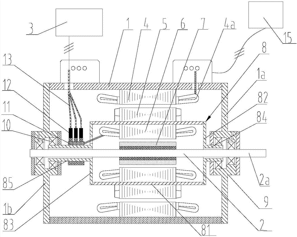
[0105] Such as image 3 As shown, the permanent magnet coupling speed regulating motor provided by the third embodiment of the present invention, the permanent magnet coupling speed regulating motor includes: a housing 1, an output shaft 2, a control structure 3, an electric structure, and a speed regulating structure; wherein, the electric structure consists of an electric The rotor 5 is composed of a stator 4 arranged on the inner wall of the casing 1, and the speed regulating structure includes a winding rotor 6 and a permanent magnet rotor 7; the magnetic field of the stator 4 interacts with the magnetic field of the electric rotor 5 to transmit torque, and the magnetic field of the winding rotor 6 and the The magnetic field of the permanent magnet rotor 7 interacts to transmit torque; the winding rotor 6 is fixedly connected to the electric rotor 5, the permanent magnet rotor 7 is fixedly connected to the output shaft 2, and the permanent magnet rotor 7, the winding rotor ...


PUM


Abstract

The invention relates to a permanent magnetic coupling adjustable-speed motor comprising a shell (1), an output shaft (2), a control structure (3), a power-driven structure and a speed adjustment structure, wherein the power-driven structure comprises an electric rotor (5) and a stator (4) arranged on the inner wall of the shell, the speed adjustment structure comprises a winding rotor (6) and a permanent magnetic rotor (7), magnetic fields of the stator and the electric rotor interact with each other to transmit the torque, and magnetic fields of the winding rotor and the permanent magnetic rotor interact with each other to transmit the torque; one of the winding rotor and the permanent magnetic rotor is fixedly connected with the electric rotor, while the other one is fixedly connected with the output shaft; the control structure is electrically connected with the winding rotor, and adjusts current or voltage of the winding rotor. The permanent magnetic coupling adjustable-speed motor can operate efficiently, is smooth in speed adjustment, large in speed adjustment range, hard in rigidity and short in axial size, and has the capacity of riding through low voltage.

Description

technical field [0001] The invention relates to the field of motors, in particular to a permanent magnet coupling speed-regulating motor. Background technique [0002] Speed ​​regulation operation is recognized as one of the best ways to realize motor energy saving. There are three main methods for motor speed regulation operation: [0003] 1. Electromagnetic speed regulation [0004] Electromagnetic speed regulation is composed of cage motor, electromagnetic slip clutch and DC excitation power supply (controller). The electromagnetic slip clutch is composed of armature, magnetic pole and excitation winding. The armature is coaxially connected with the cage motor rotor and driven by the cage motor. The magnetic pole is connected to the load through the coupling, and the excitation winding is connected to DC. When the armature rotates with the cage motor, due to the relative motion between the armature and the magnetic poles, the armature induces eddy current, which interac...

Claims


Application Information

Patent Timeline
Patent Type & Authority Applications(China)
IPC IPC(8): H02K49/10H02K1/27H02K3/28H02K16/00
CPCH02K1/272H02K3/28H02K16/00H02K49/104
Inventor 徐俊峰陈超漆复兴
Owner JIANGSU MAGNET VALLEY TECH
Why Eureka
Try Eureka