
Sports monitoring system and manufacturing method thereof

A motion monitoring and production method technology, which is applied in motion accessories, chemical instruments and methods, and other household appliances, can solve the problems of increased work costs, limited information, and unsuitable motion monitoring and identification for amputee patients, and achieves a simple and light structure. The effect of saving, simple and light structure

Pending Publication Date: 2017-11-07
SHENZHEN INST OF ADVANCED TECH
View PDF3 Cites 3 Cited by
  • Summary
  • Abstract
  • Description
  • Claims
  • Application Information

AI Technical Summary

Problems solved by technology

Although the accelerometer can record the multi-directional acceleration data of the human limbs, it cannot provide other motion information, so the information obtained is very limited; the data glove is embedded with an inertial sensor and a bending sensor, which can identify more fine human movements, but Its disadvantage is that it is too cumbersome, and it is not suitable for the movement monitoring and recognition of amputee patients; surface electromyography is a relatively mature and widely used method for human movement monitoring. The signal of command information is then used to monitor the progress of rehabilitation activities or to control human-computer interaction equipment and myoelectric prosthetics. However, surface myoelectricity has the following insurmountable problems: it is very difficult to place the electrodes that extract myoelectricity. High requirements and high-level signal feature extraction increase the cost of work, human muscle fatigue will increase the difficulty of signal acquisition and reduce the reliability of the extracted control command signal, electromagnetic interference and changes in conductivity will also affect the quality of the signal; The force diagram method is the most promising monitoring method for compensating or even replacing surface electromyography. Its biggest advantage is that it can directly reflect the changes of muscles during exercise and has a high response speed. However, the existing It is difficult for any sensor that uses the muscle force map method to monitor human body movement in real time to have the performance advantages of high measurement accuracy and simple and light structure.

Method used


Image

  • Sports monitoring system and manufacturing method thereof
  • Sports monitoring system and manufacturing method thereof
  • Sports monitoring system and manufacturing method thereof

Examples


Embodiment 1

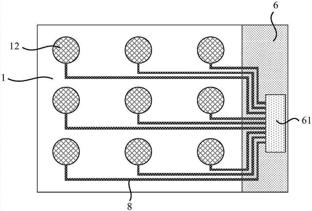
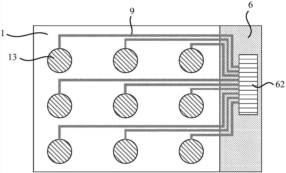
[0027] figure 1 A schematic cross-sectional structure diagram of a motion monitoring system provided by Embodiment 1 of the present invention, as shown in figure 1 As shown, the motion monitoring system includes: a pressure-sensitive film detection layer 11, a first metal electrode array 12 is provided on the upper surface of the pressure-sensitive film detection layer 11, and a second metal electrode array 13 is provided on the lower surface of the pressure-sensitive film detection layer 11 , the first metal electrode array 12 , the second metal electrode array 13 and the pressure-sensitive thin film detection layer 11 together form a pressure sensing array 1 for collecting pressure signals.

[0028] see Figure 2A and Figure 2B , the motion monitoring system also includes a signal processing module 6, the first signal input end 61 of the signal processing module 6 is electrically connected to the first metal electrode array 12, the second signal input end 62 of the signal...

Embodiment 2

[0036] image 3 A schematic cross-sectional structure diagram of a motion monitoring system provided by Embodiment 2 of the present invention, as shown in image 3 As shown, on the basis of the above-mentioned technical solutions, this embodiment also includes: a first shielding layer 2 and a second shielding layer 3; One side, and is insulated from the first metal electrode array 12; The second shielding layer 3 is located on the side of the second metal electrode array 13 away from the pressure-sensitive film detection layer 11, and is insulated from the second metal electrode 13 array; the first shielding layer 2 and the second shielding layer 3 are connected to the negative pole of the power supply of the signal processing module ( image 3 not shown) electrical connections.

[0037] Specifically, the size of the first shielding layer 2 is the same as that of the pressure sensing array 1 , and the size of the second shielding layer 3 is the same as that of the pressure s...

Embodiment 3

[0043] Figure 4 A three-dimensional schematic diagram of the detection layer of the pressure-sensitive film in the motion monitoring system provided by Embodiment 3 of the present invention. In this embodiment, on the basis of the above-mentioned embodiments, the pressure-sensitive film detection layer 11 further includes a polyvinylidene fluoride film, a polyvinylidene fluoride copolymer film or a piezoelectric electret film. The pressure-sensitive thin-film detection layer 11 can be formed by laminating one or more than one of the above-mentioned thin films in series or in parallel.

[0044] On the basis of the above technical solutions, the piezoelectric electret film includes at least one of polypropylene, polyethylene terephthalate or polyethylene terephthalate.

[0045] On the basis of the above technical solutions, the piezoelectric electret film is a single-layer porous film or a multi-layer porous film. Multilayer porous membranes are stacked in parallel or in seri...


PUM


Abstract

The invention discloses a sports monitoring system and a manufacturing method thereof. The sports monitoring system comprises a pressure-sensitive film detection layer and a signal processing module. A first metal electrode array and a second metal electrode array are arranged on the upper surface and the lower surface of the pressure-sensitive film detection layer respectively. A first signal input end of the signal processing module is electrically connected with the first metal electrode array, and a second signal input end of the signal processing module is electrically connected with the second metal electrode array. The sports monitoring system is simple in structure, high in sensitivity, almost free of pyroelectric effect, almost insusceptible to temperature variation in an operating temperature range, sensitive to force in the vertical direction, insensitive to shear force in the horizontal direction and insusceptible to material bending in vertical pressure detection, and high-precision measurement of sports information is realized.

Description

technical field [0001] Embodiments of the present invention relate to information monitoring technology, in particular to a motion monitoring system and a manufacturing method thereof. Background technique [0002] With the development and progress of social science and technology, people pay more and more attention to their own health and quality of life, and the level of physical fitness of the human body can most intuitively show the level of personal health. The monitoring of human motion can reflect the health status of the human motion system in real time and effectively. At the same time, since the monitoring and identification information of human body contains the individual's willingness to control motion, the processing and processing of these information can also be used to control multiple Functional intelligent prosthetics, exoskeleton walkers or other human-computer interaction devices to help disabled patients or the elderly recover their health, especially t...

Claims


Application Information

Patent Timeline
Patent Type & Authority Applications(China)
IPC IPC(8): A61B5/22A61B5/11B32B15/04B32B33/00
CPCA61B5/1107A61B5/22B32B15/04B32B33/00B32B2307/206B32B2457/00
Inventor 方鹏张楠鑫李向新李光林
Owner SHENZHEN INST OF ADVANCED TECH
Learn More