Concrete slurry stirring and processing device for bridge construction

A technology for bridge construction and processing equipment, which is applied in bridge construction, bridges, clay preparation devices, etc. It can solve the problems of affecting the mixing effect, inconvenient moving and positioning, and increasing the cost of equipment use, so as to increase the mixing effect and prevent heat loss. , The effect of material activity enhancement

Inactive Publication Date: 2017-11-07
童贤波
View PDF0 Cites 20 Cited by
  • Summary
  • Abstract
  • Description
  • Claims
  • Application Information

AI Technical Summary

Problems solved by technology

[0002] In bridge machinery, the concrete slurry is composed of cement, fine aggregate and water, and the concrete prepared on site according to the needs of lime, active admixtures or admixtures is divided into concrete slurry and cement mixed concrete. In construction engineering, the first is foundation and wall masonry, which is used as an adhesive for block masonry materials, such as concrete slurry for masonry and red bricks, and the second is for indoor and outdoor plastering, but existing The structure and function of the advanced concrete slurry mixing equipment are simple and single. The mixing mechanism in the inner cavity only has the mixing effect of a single layer of material, and cannot perform all-round mixing treatment at all. Some slurry bonded to the side wall or bottom wall Effective mixing cannot be carried out, not only the internal mixing effect is poor, but also it is easy to cause waste of materials.

Method used


Image

  • Concrete slurry stirring and processing device for bridge construction
  • Concrete slurry stirring and processing device for bridge construction
  • Concrete slurry stirring and processing device for bridge construction

Examples


Embodiment Construction

[0017] The following will clearly and completely describe the technical solutions in the embodiments of the present invention with reference to the accompanying drawings in the embodiments of the present invention. Obviously, the described embodiments are only some, not all, embodiments of the present invention. Based on the embodiments of the present invention, all other embodiments obtained by persons of ordinary skill in the art without making creative efforts belong to the protection scope of the present invention.

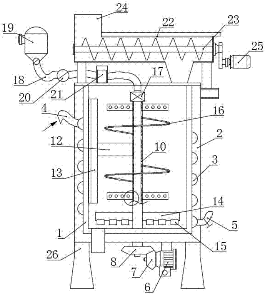
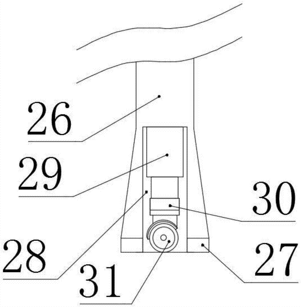
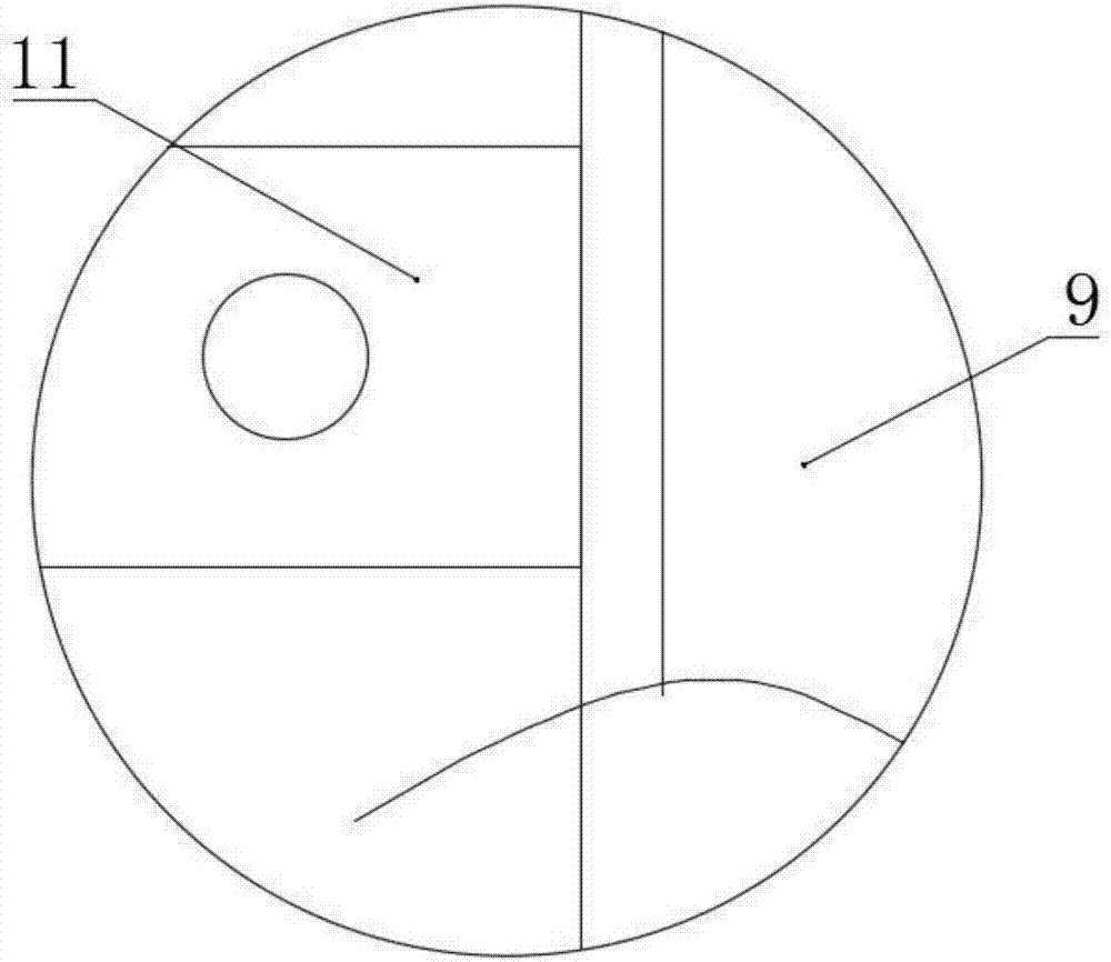
[0018] see Figure 1-3 , in an embodiment of the present invention, a concrete slurry mixing and processing equipment for bridge construction, comprising a mixing shell 1, the outer shell of the mixing shell 1 is provided with an outer thermal insulation layer 2, and the outer thermal insulation layer 2 There are grooves on both sides of the casing, and the outer wall of the mixing shell 1 is provided with a heating coil 3 arranged in a spiral shape. Adaptati...


PUM


Abstract

The invention discloses a concrete slurry mixing and processing equipment for bridge construction, which comprises a mixing shell, the outer wall of the mixing shell is provided with a heating coil arranged in a spiral shape, and the inside of the mixing shaft is provided with a Hollow structure and several small spraying holes are opened on the outer wall of the shaft body, a flow control switch and a small water pump are installed on the body of the water delivery pipeline, and plate-type stirring blades are respectively arranged on both sides of the upper and lower shaft body of the mixing shaft And the spiral mixing blade, the end of the horizontal support rod is equipped with a strip scraper, the upper part of the mixing shell is also fixedly equipped with a premix conveyor, and the lower end of the hydraulic telescopic rod is equipped with a universal roller through a connecting sleeve. The invention can achieve rapid temperature rise, realize automatic cleaning of the inner cavity after work, fully stir, improve the mixing effect of subsequent materials, facilitate moving and positioning, and save time and effort.

Description

technical field [0001] The invention relates to the technical field related to construction machinery and equipment, in particular to concrete slurry mixing and processing equipment for bridge construction. Background technique [0002] In bridge machinery, the concrete slurry is composed of cement, fine aggregate and water, and the concrete prepared on site according to the needs of lime, active admixtures or admixtures is divided into concrete slurry and cement mixed concrete. In construction engineering, the first is foundation and wall masonry, which is used as an adhesive for block masonry materials, such as concrete slurry for masonry and red bricks, and the second is for indoor and outdoor plastering, but existing The structure and function of the advanced concrete slurry mixing equipment are simple and single. The mixing mechanism in the inner cavity only has the mixing effect of a single layer of material, and cannot perform all-round mixing treatment at all. Some s...

Claims


Application Information

Patent Timeline
IPC IPC(8): B28C5/16B28C5/46B28C7/00B28C7/10E01D21/00
CPCB28C5/16B28C5/466B28C7/00B28C7/0007B28C7/10E01D21/00
Inventor 童贤波
Owner 童贤波
Why Eureka
Try Eureka