Dewatering device for paper making

A technology of dehydration device and suction roller, which is applied in papermaking, papermaking machines, textiles and papermaking, etc. It can solve the problems of poor dehydration ability affecting paper processing and product quality, affecting the effect of wet paper pressing, and low paper compactness. Achieve enhanced dehydration effect, improve dehydration efficiency, and reduce drying energy consumption

Inactive Publication Date: 2017-11-07
钟敏芝
View PDF8 Cites 2 Cited by
  • Summary
  • Abstract
  • Description
  • Claims
  • Application Information

AI Technical Summary

Problems solved by technology

[0002] With the development of society and the improvement of people's living standards, the market has put forward higher and higher requirements for the quality of paper. In the paper industry, paper still contains a large amount of water after it is formed in the wire section. Before drying, the formed wet paper needs to be further dehydrated by pressing through the press section, so that the wet paper is not easy to break and crack when it enters the drying section of the dryer, and the dehydrated wet paper is further pressed by the press section Entering the drying section of the drying cylinder can save the heat of the drying section of the drying cylinder and improve the drying efficiency of the paper sheet. If it is directly sent to the drying without pre-dehydration, a large amount of steam will be consumed, and the resulting

Method used


Image

  • Dewatering device for paper making
  • Dewatering device for paper making
  • Dewatering device for paper making

Examples


Example Embodiment

[0016] The specific embodiments of the present invention will be further described below with reference to the accompanying drawings. It should be noted here that the descriptions of these embodiments are used to help the understanding of the present invention, but do not constitute a limitation of the present invention. In addition, the technical features involved in the various embodiments of the present invention described below can be combined with each other as long as they do not conflict with each other.

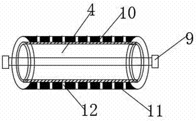
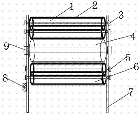
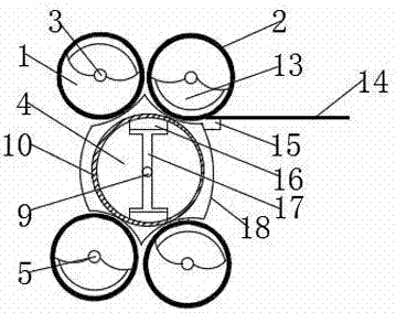
[0017] see figure 1 , figure 2 and image 3 , The present invention provides a technical solution: a dewatering device for papermaking, comprising a bracket 7, a driven water suction roller group 1 is arranged on the upper surface of the bracket 7, and a belt drive shaft 15 is arranged on the right side of the driven water suction roller group 1, A belt 14 for conveying paper is arranged on the belt transmission shaft 15, and a driven suction roller shaft 3 is arr...


PUM


Abstract

The invention discloses a dewatering device for paper making. The device includes a support, a driven water absorbing roller group is arranged above the support, and the outer side of the circumference of each driven water absorbing roller is wrapped with a water absorbing material layer; a press roller is arranged at the lower side of the driven water absorbing roller group, and the driven water absorbing roller group is mutually squeezed with the press roller; the interior of the press roller is provided with a pressing boot, a boot beam is arranged below the pressing boot, and the upper end of the boot beam abuts against the lower end of the pressing boot to support the pressing boot; a boot sleeve is arranged on the periphery of the pressing boot in a wrapping mode, and a water absorbing layer and a plastic layer are arranged on the surface of the outer circumference of the press roller successively from inside to outside; the interior of the plastic layer is provided with a micro circular hole, a driving water absorbing roller group is arranged below the press roller, and a servo numerical control motor is arranged on the left side of a driving water absorbing roller shaft. The dewatering device for paper making is simple in structure, can effectively remove moisture in wet paper pages, and greatly reduces production energy consumption.

Description

technical field [0001] The invention relates to the technical field of papermaking equipment, in particular to a dewatering device for papermaking. Background technique [0002] With the development of society and the improvement of people's living standards, the market has put forward higher and higher requirements for the quality of paper. In the papermaking industry, the paper sheet still contains a lot of moisture after it is formed in the wire section, and it enters the drying section of the dryer. Before drying, the formed wet paper sheet needs to be further dehydrated by pressing through the pressing section, so that the wet paper sheet is not easily broken and cracked when entering the drying section of the dryer, and the dehydrated wet paper sheet is further pressed by the pressing section. Entering the drying section of the drying cylinder can save the heat of the drying section of the drying cylinder and improve the drying efficiency of the paper sheet. If it is d...

Claims


Application Information

Patent Timeline
IPC IPC(8): D21F3/02D21F3/08D21F3/10D21F3/04
Inventor 钟敏芝
Owner 钟敏芝
Why Eureka
Try Eureka