Energy-saving internal combustion engine crankshaft mechanism capable of increasing torque

An internal combustion engine and crankshaft technology, applied in the field of internal combustion engines, can solve the problems of low torque, waste of energy, affecting the torque power output of the internal combustion engine, etc., and achieve the effect of improving energy conversion rate and high torque

Pending Publication Date: 2017-11-07
刘洪保
View PDF9 Cites 1 Cited by
  • Summary
  • Abstract
  • Description
  • Claims
  • Application Information

AI Technical Summary

Problems solved by technology

[0002] In a traditional internal combustion engine, the pressure generated when the cylinder explodes works through the external output torque of the piston, connecting rod and crankshaft, and the force arm of the cylinder pressure to the crankshaft moment increases gradually from zero to the bottom dead center. , and then gradually return to zero, that is to say, when a crank of the crankshaft reaches the top dead center, the axis of the connecting rod connected to the crank of the crankshaft passes through the center of the crankshaft, and the piston connecte

Method used


Image

  • Energy-saving internal combustion engine crankshaft mechanism capable of increasing torque
  • Energy-saving internal combustion engine crankshaft mechanism capable of increasing torque
  • Energy-saving internal combustion engine crankshaft mechanism capable of increasing torque

Examples


Example Embodiment

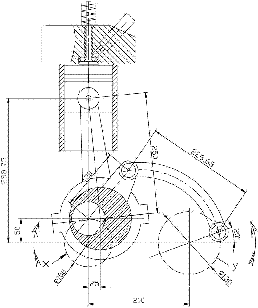
[0031] Take the eccentricity of crankshaft 1 of 50mm, eccentricity of eccentric sleeve body 4 of 25mm, eccentricity of tie rod small crankshaft 3 of 65mm, tie rod 5 hole distance of 226.68mm, and crankshaft 1 and tie rod small crankshaft 3 of center distance of 210mm as an example. Be explained.

[0032] See figure 1 The shown energy-saving and torque-increasing internal combustion engine crankshaft mechanism includes a crankshaft 1, an eccentric sleeve body 4, a tie rod 5 and a tie rod small crankshaft 3, a connecting rod 2, and a piston 7.

[0033] Two meshing gears 6 with the same number of teeth are respectively connected to the same end of the crankshaft 1 and the small crankshaft 3 of the pull rod by keys. In order to prevent the outer diameter of the gear 6 from being too large, an even number of meshing gears 6 can be arranged between the crankshaft 1 and the small lever crankshaft 3 for transmission, so that the crankshaft 1 and the small lever crankshaft 3 rotate at the s...


PUM


Abstract

The invention provides an energy-saving internal combustion engine crankshaft mechanism capable of increasing the torque. The energy-saving internal combustion engine crankshaft mechanism comprises a crankshaft, an eccentric sleeve body, a pull rod, a small pull rod crankshaft, a connecting rod and a piston. The eccentric sleeve body is provided with an inner hole matched with a crank of the crankshaft. The axis of an outer circle of the eccentric sleeve body and the axis of the inner hole are in an eccentric state. The connecting rod is mounted on the outer circle of the eccentric sleeve body. The other end of the connecting rod is connected with the piston. One end of the pull rod is hinged to an eccentric sleeve body arm of the eccentric sleeve body, and the other end of the pull rod is hinged to a crank of the small pull rod crankshaft. The crankshaft and the small pull rod crankshaft rotate at constant angular velocity. The eccentric sleeve body swings with the axis of the inner hole as the axis. When the crank of the crankshaft rotates to the upper dead center, the piston does not reach the upper dead center position due to the action of the eccentric sleeve body; and the piston reaches the upper dead center position when the crank of the crankshaft rotates by the angle alpha being 12 to 38 degrees with the position where the crank of the crankshaft is in the upper dead center as a benchmark. When an internal combustion engine nears the upper dead center of the piston, large arm of force is achieved, high gas pressure is also achieved, and large torque can be output.

Description

technical field [0001] The technology relates to the field of internal combustion engines, in particular, an internal combustion engine crankshaft mechanism capable of saving fuel consumption and increasing torque. Background technique [0002] In a traditional internal combustion engine, the pressure generated when the cylinder explodes works through the external output torque of the piston, connecting rod and crankshaft, and the force arm of the cylinder pressure to the crankshaft moment increases gradually from zero to the bottom dead center. , and then gradually return to zero, that is to say, when a crank of the crankshaft reaches the top dead center, the axis of the connecting rod connected to the crank of the crankshaft passes through the center of the crankshaft, and the piston connected to the connecting rod also goes up. At the dead center position, the gas combustion pressure in the cylinder is very high at this time, but the moment arm is very small, so the torqu...

Claims


Application Information

Patent Timeline
IPC IPC(8): F02B75/32F02B75/16F02B75/18F16H21/18F16C3/22F16C7/02
CPCF02B75/16F02B75/18F02B75/32F16C3/22F16C7/023F16H21/18Y02T10/12
Inventor 刘洪保
Owner 刘洪保
Why Eureka
Try Eureka