Small process for generating gas through light hydrocarbon gas generating

A technology for gas generation and light hydrocarbons, applied in combustion methods, combustion equipment, fuel supply, etc., can solve the problems of easy generation of condensed oil, aggravated condensed oil, different calorific value of gas, etc., to accelerate volatilization and solve the phenomenon of condensed oil. , the effect of stable gas quality

Inactive Publication Date: 2017-11-07
SHANDONG UNIV OF TECH
View PDF4 Cites 4 Cited by
  • Summary
  • Abstract
  • Description
  • Claims
  • Application Information

AI Technical Summary

Problems solved by technology

The technical problems currently faced by this method are: 1. Light hydrocarbon gas itself is not suitable for long-distance pipeline transmission. Generally, the transmission distance is preferably no more than 100 meters, and the pipeline for home users is usually more than one kilometer due to factors such as safety distance; 2. Gas is prone to oil condensation during pipeline transmission, and gas production stations usually use pressurization to increase pipeline transmission distance, and pressurization itself will aggravate oil condensation
3. The above situation will lead to different calorific values ​​of the gas entering the pipelines of various household users. At the same time, the condensed oil in the pipelines will often be brought into the pipelines of users, resulting in black smoke from combustion.
Therefore, there are basically no successful cases of light hydrocarbon gas used in households

Method used


Image

  • Small process for generating gas through light hydrocarbon gas generating

Examples


Embodiment 1

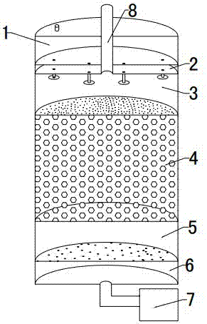
[0023] Fill the liquid light hydrocarbon raw material into the light hydrocarbon raw material chamber 1. When it needs to be used, turn on the control switch, the oil delivery booster pump starts to work, the fuel injection nozzle starts to spray the liquid light hydrocarbon raw material, and the liquid light hydrocarbon raw material is evenly sprinkled on the On the upper dividing plate of the porous ceramic material chamber 4, it enters the porous ceramic material chamber 4 from the pores, and continuously flows downward under the action of gravity to form an oil film on the surface of the porous ceramic material. Controlled by the circuit board, start the hot air blower 7 and start sending hot air 11s after the fuel injection nozzle starts to spray. The air supply volume is 1L. The hot air passes through the rectifying chamber 6 and the steady flow chamber 5 successively to form a steadily rising hot air flow. After entering the porous ceramic material chamber 4, the hot ai...

Embodiment 2

[0025] Fill the liquid light hydrocarbon raw material into the light hydrocarbon raw material chamber 1. When it needs to be used, turn on the control switch, the oil delivery booster pump starts to work, the fuel injection nozzle starts to spray the liquid light hydrocarbon raw material, and the liquid light hydrocarbon raw material is evenly sprinkled on the On the upper dividing plate of the porous ceramic material chamber 4, it enters the porous ceramic material chamber 4 from the pores, and continuously flows downward under the action of gravity to form an oil film on the surface of the porous ceramic material. Controlled by the circuit board, start the hot air blower 7 and start sending hot air 15s after the fuel injection nozzle starts to spray oil. The supply air volume is 0.7 L. The hot air passes through the rectifying chamber 6 and the steady flow chamber 5 successively to form a steadily rising hot air flow. After entering the porous ceramic material chamber 4, the...

Embodiment 3

[0027]Fill the liquid light hydrocarbon raw material into the light hydrocarbon raw material chamber 1. When it needs to be used, turn on the control switch, the oil delivery booster pump starts to work, the fuel injection nozzle starts to spray the liquid light hydrocarbon raw material, and the liquid light hydrocarbon raw material is evenly sprinkled on the On the upper dividing plate of the porous ceramic material chamber 4, it enters the porous ceramic material chamber 4 from the pores, and continuously flows downward under the action of gravity to form an oil film on the surface of the porous ceramic material. Controlled by the circuit board, start the hot air blower 7 and start sending hot air 8 seconds after the fuel injection nozzle starts to spray oil. The air supply volume is 1.3L. The hot air passes through the rectifying chamber 6 and the steady flow chamber 5 successively to form a steadily rising hot air flow. After entering the porous ceramic material chamber 4,...


PUM


Abstract

The invention discloses a small process for generating gas through light hydrocarbon gas generating, and belongs to the technical field of gas generating equipment. The process is characterized in that a light hydrocarbon raw material chamber (1), a control chamber (2), a spray chamber (3), a porous ceramic material chamber (4), a flow stabilizing chamber (5) and a rectifying chamber (6) are sequentially arranged in a tank body from top to bottom, wherein the height of the porous ceramic material chamber (4) is 45cm-55cm; the bottom opening of the rectifying chamber (6) is connected with a hot air blower (7); and an upward gas output pipe (8) is arranged at the spray chamber (3). Liquid light hydrocarbon raw materials are added to the light hydrocarbon raw material chamber (1), the hot air blower (7) is started to supplying air 8s-15s after the oil injection of a nozzle, and the hot air and the liquid light hydrocarbon are volatilized and gasified to produce mixed air gas. The independent and small light hydrocarbon gas generating equipment and the gas generating process can be used independently by a family with stable gas quality.

Description

technical field [0001] The invention relates to a small-scale light hydrocarbon gas generation and gas production process, which belongs to the technical field of gas generation equipment. Background technique [0002] The light hydrocarbon gas generation system uses liquid light hydrocarbons (mainly composed of C5) as raw materials, and converts liquid light hydrocarbons into air-mixed gas through special gasification equipment, so as to improve combustion efficiency and realize full utilization of existing energy. The existing fuel gas generating device is basically a bubbling type, that is, the air is blown into the gas generating tank, and when the bubbles rise in the oil, the oil contacts the bubbles, and the oil molecules enter the bubbles to form a combustible air-mixed light hydrocarbon gas. In order to ensure the quality (calorific value) of fuel gas, the common method is to increase the contact area between gas and oil and increase the residence time of bubbles in...

Claims


Application Information

Patent Timeline
Patent Type & Authority Applications(China)
IPC IPC(8): F23K5/22
CPCF23K5/22F23K2300/205
Inventor 万隆巴奉军张鹏成曙光
Owner SHANDONG UNIV OF TECH
Why Eureka
Try Eureka