
Spraying demonstration device of adopting machine vision and fiber optic gyroscope to position cooperatively

A fiber optic gyroscope and machine vision technology, applied in the direction of using optical devices, measuring devices, instruments, etc., can solve the problems of high job dependence of programming engineers, complex structure of teaching equipment, insufficient working range, etc., to simplify teaching equipment. structure, improve equipment flexibility, and improve the effect of flexibility

Pending Publication Date: 2017-11-07
HANGZHOU GUOCHEN ROBOT TECH CO LTD
View PDF1 Cites 7 Cited by
  • Summary
  • Abstract
  • Description
  • Claims
  • Application Information

AI Technical Summary

Problems solved by technology

[0002] In the prior art, the application programming of multi-axis spraying manipulators in the spraying industry is basically completed by programmers by manipulating programmers (teaching boxes) or using dedicated offline programming software. Users need to have higher knowledge and skills, and must Can only be competent after special training, highly dependent on the position of programming engineer and the operation is not intuitive, it is not easy to modify the program after setting
[0003] The telescopic spraying teaching mechanism (CN201620587905.8) previously proposed by our company with a hemispherical operating range has problems such as complex structure, high cost, and insufficient operating range.

Method used


Image

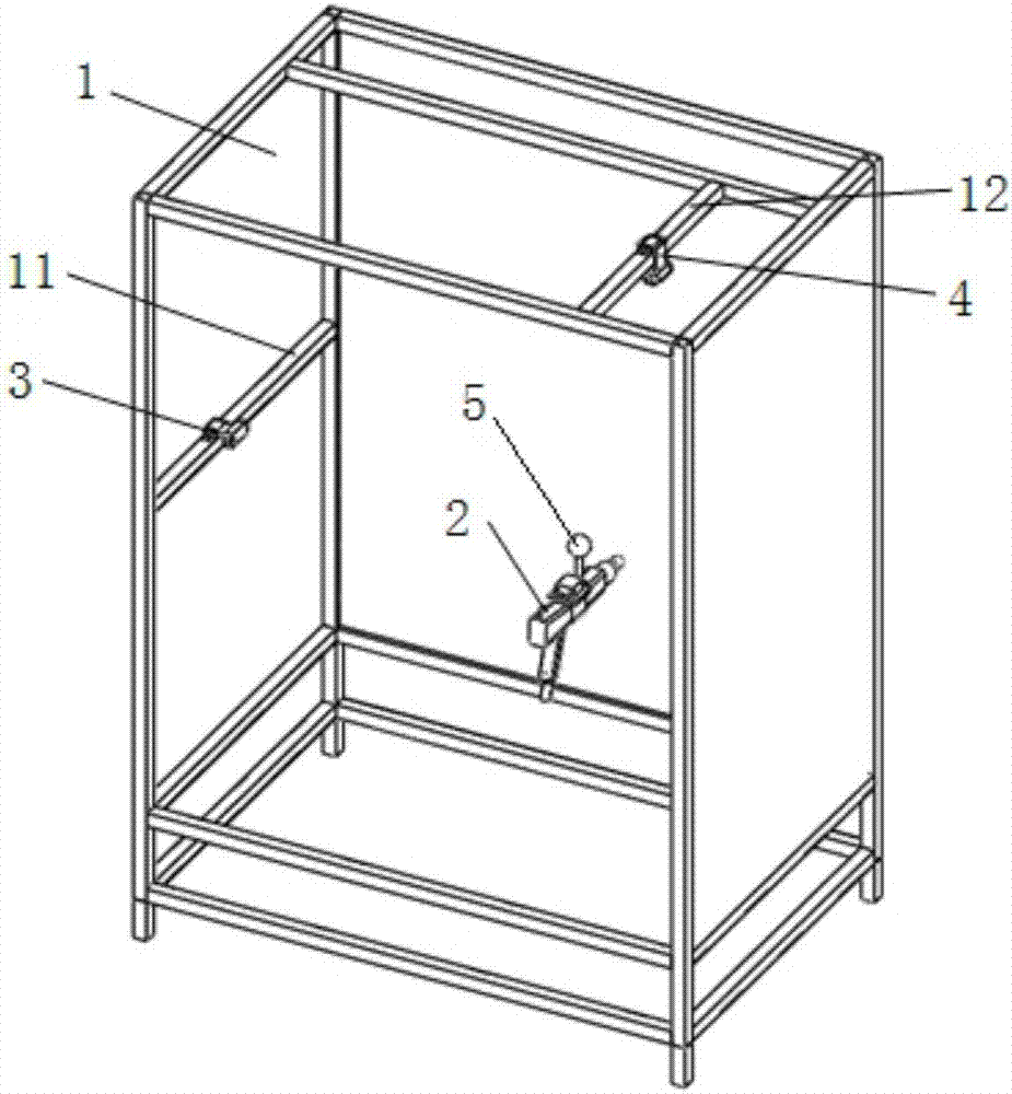
  • Spraying demonstration device of adopting machine vision and fiber optic gyroscope to position cooperatively
  • Spraying demonstration device of adopting machine vision and fiber optic gyroscope to position cooperatively

Examples


Embodiment Construction

[0021] The following will clearly and completely describe the technical solutions in the embodiments of the present invention with reference to the drawings in the embodiments of the present invention.

[0022] The present invention provides a spraying teaching device that uses machine vision and an optical fiber gyroscope for positioning. Its working principle is to obtain the coordinate parameters of the spray gun device by using the first camera and the second camera to replace the complicated mechanical mechanism in the prior art. The fiber optic gyroscope obtains the attitude parameters of the spray gun device, and the multi-axis controller obtains the coordinate parameters and attitude parameters to drive the manipulator to reproduce the operation process of the teaching mechanism. The flexibility of the multi-axis manipulator spraying operation mode achieves the purpose of simplifying the structure of the teaching equipment, reducing production costs, improving equipment...


PUM


Abstract

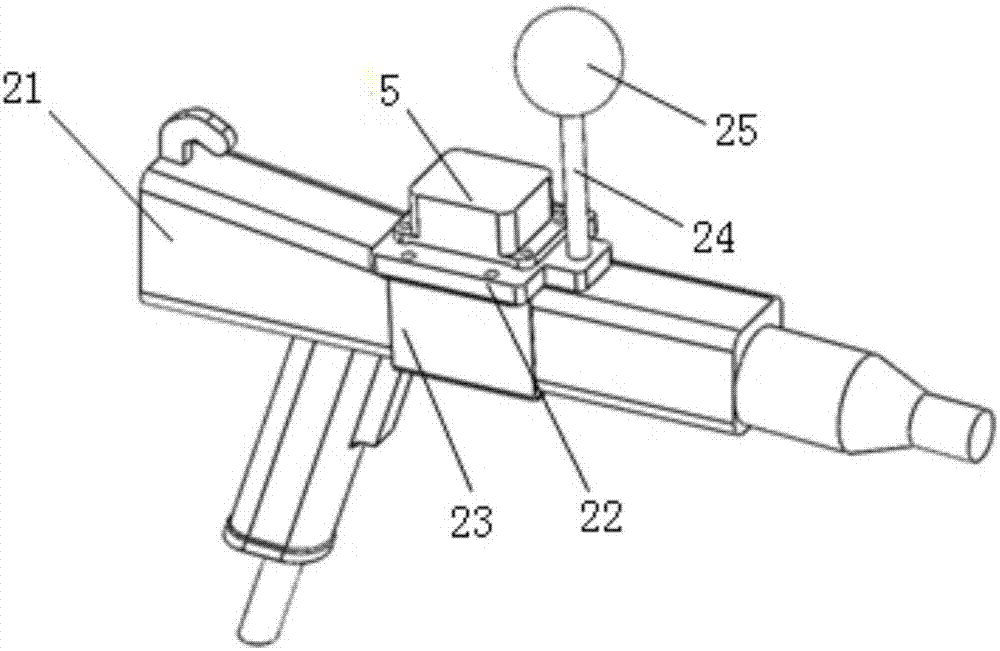
The present invention discloses a spraying demonstration device of adopting the machine vision and a fiber optic gyroscope to position cooperatively. The spraying demonstration device comprises a demonstration powder room on which a spray gun device is arranged, a first camera is arranged on the side wall of the demonstration powder room, and a second camera is arranged at the top of the demonstration powder room. The spray gun device is equipped with the fiber optic gyroscope used for acquiring the poses of a demonstration spray gun, and the fiber optic gyroscope is connected with an external multi-shaft controller. According to the present invention, by utilizing the first camera and the second camera to substitute for the complicated mechanical mechanisms in the prior art to obtain the coordinate parameters of the spray gun device, and utilizing the fiber optic gyroscope to obtain the pose parameters of the spray gun device, and using the multi-shaft controller to obtain the coordinate parameters and the pose parameters and then drive a manipulator to reappear the operation process of a demonstration mechanism, the defects that a conventional multi-shaft manipulator is complicated in demonstration mode, the technical requirements are high, etc., can be solved, the flexibility of a multi-shaft manipulator spraying working mode is improved, and the purposes of simplifying the structure of the demonstration device, reducing the production cost, improving the flexibility of the demonstration device and expanding the working range are achieved.

Description

technical field [0001] The invention relates to a teaching device used in the spraying industry, in particular to a spraying teaching device which uses machine vision and an optical fiber gyroscope for positioning. Background technique [0002] In the prior art, the application programming of multi-axis spraying manipulators in the spraying industry is basically completed by programmers by manipulating programmers (teaching boxes) or using dedicated offline programming software. Users need to have higher knowledge and skills, and must Only after special training can they be competent. It is highly dependent on the position of a programming engineer and the operation is not intuitive. After the program is set, it is not easy to modify. [0003] The telescopic spraying teaching mechanism (CN201620587905.8) previously proposed by our company with a hemispherical operating range has problems such as complex structure, high cost, and insufficient operating range. Contents of th...

Claims


Application Information

Patent Timeline
IPC IPC(8): G01B11/00G01C11/00G01C21/18G09B25/02
CPCG09B25/02G01B11/002G01C11/00G01C21/18
Inventor 刘志斌刘腾君金学军傅正珂裴翔王国成
Owner HANGZHOU GUOCHEN ROBOT TECH CO LTD
Learn More