
Constant-pressure hard rail system utilizing gas-liquid two-phase annular flow effect

A kind of annular flow, effect technology, applied in the direction of large fixed members, metal processing machinery parts, maintenance and safety accessories, etc., can solve the problems of low working efficiency, poor durability, and large consumption of lubricating oil of ordinary hard rails, and improve the The effect of positioning accuracy and repeat positioning accuracy, low manufacturing cost, and reduced oil consumption

Active Publication Date: 2017-11-10
CHINA FIRST AUTOMOBILE
View PDF5 Cites 4 Cited by
  • Summary
  • Abstract
  • Description
  • Claims
  • Application Information

AI Technical Summary

Problems solved by technology

[0008] The purpose of the present invention is to overcome the above disadvantages, thereby providing a constant pressure hard rail system utilizing the gas-liquid two-phase annular flow effect, which has a simple structure, good lubrication effect, fast moving speed, and energy saving, and can effectively solve the problem of Ordinary hard rails have problems such as low working efficiency, large lubricating oil consumption, and poor durability, which reduces the cost of equipment use and can be applied to heavy-duty cutting and precision machining at the same time

Method used


Image

  • Constant-pressure hard rail system utilizing gas-liquid two-phase annular flow effect
  • Constant-pressure hard rail system utilizing gas-liquid two-phase annular flow effect
  • Constant-pressure hard rail system utilizing gas-liquid two-phase annular flow effect

Examples


Embodiment Construction

[0027] Below the present invention will be further described in conjunction with the embodiment in the accompanying drawing:

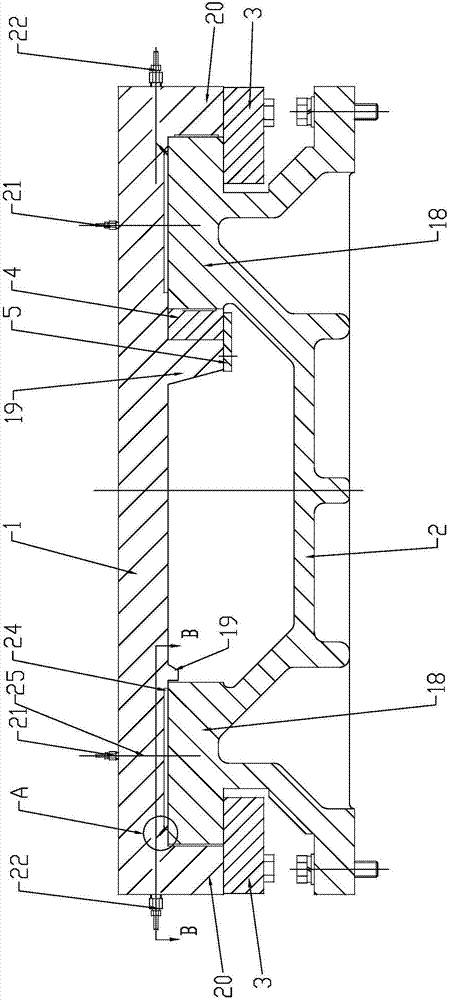
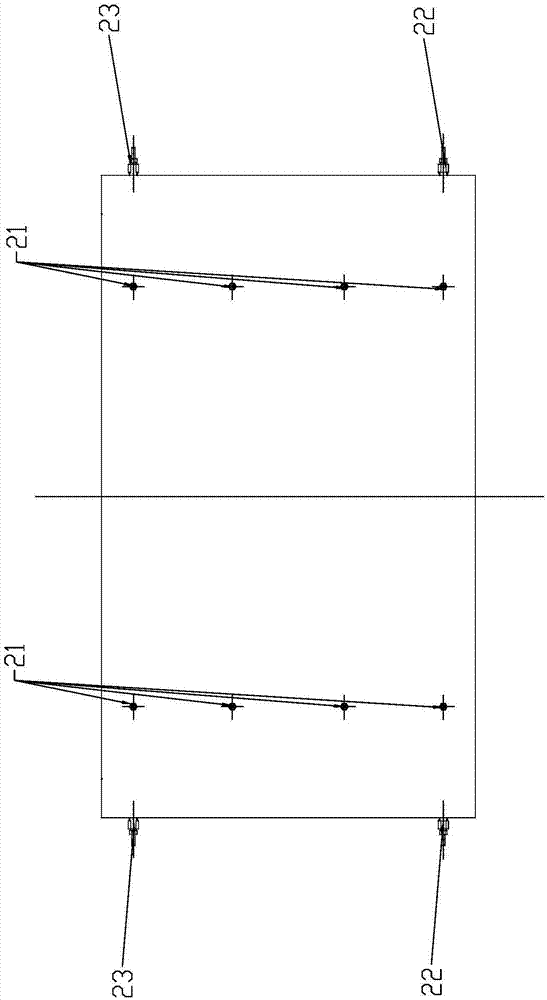
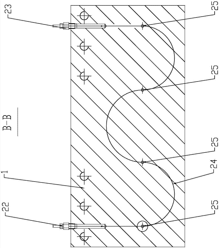
[0028] like Figure 1~5 As shown, the present invention mainly includes a slide table 1, a base 2, a gas source 6, a gas shunt 11, a lubricating oil station 15 and an oil separator 17.

[0029] The upper end of the base 2 is provided with two left and right guide rails 18 , and the lower end surface of the sliding table 1 is slidably connected to the two guide rails 18 of the base 2 . The slide table 1 is provided with a lubricating groove 24 on the end faces of the two guide rails 18 .

[0030] The surface roughness of the contact end surface of the slide table 1 and the guide rail 18 is Ra1.6~Ra3.2, and the number of grinding points within the range of 25mm×25mm is more than 10. This surface topography of the slide table 1 is more conducive to the formation of oil-air mixed oil film.

[0031] A baffle structure is respectively provided on the side...


PUM


Abstract

The invention relates to a guide rail structure, in particular to a constant-pressure hard rail system utilizing the gas-liquid two-phase annular flow effect, and belongs to the technical field of guide rail structures of machine tools. The system comprises a sliding platform, a base, a gas source, a gas divider, a lubricating oil station and an oil distributor; a left guide rail and a right guide rail are arranged at the upper end of the base; the lower end surface of the sliding platform is glidingly connected onto the two guide rails of the base; lubricating grooves are formed in the end surface, facing the two guide rails, of the sliding platform; a gas inlet and a gas outlet of each of gas inlet and outlet groups on the left and right sides of the sliding platform communicate with the corresponding lubricating groove through gas channels formed in the sliding platform; and four oil inlets of an oil inlet group on the side corresponding to each gas inlet and outlet group communicate with the lubricating groove on the side through oil channels. With the system, the required gas flow under certain pressure and at certain flow is guaranteed, the gas flow and lubricating oil under certain pressure form the annular flow state, which is the state that the gas is coated with the lubricating oil, in the gas-liquid two-phases, the lubricating effect can be effectively improved, and about 50% of the lubricating oil consumption can be reduced.

Description

technical field [0001] The invention relates to a guide rail structure, in particular to a constant-pressure hard rail system utilizing the gas-liquid two-phase annular flow effect, and belongs to the technical field of machine tool guide rail structures. Background technique [0002] The guide rails used in metal cutting machine tools mainly include rolling guide rails, hard rails, plastic-coated guide rails, static pressure and unloading guide rails. Each guide rail has its own disadvantages and advantages: [0003] 1. Hard rails, hard rails refer to metal-to-metal contact and sliding friction guide rails. This kind of guide rail has a simple structure, large load capacity, and good stability, but the metal-to-metal contact lubrication effect is not good, and the friction force is large, resulting in moving speed. Slow, fast wear, prone to crawling phenomenon; [0004] 2. Rolling guide rail, this kind of guide rail structure belongs to point-surface contact, fast moving s...

Claims


Application Information

Patent Timeline
Patent Type & Authority Applications(China)
IPC IPC(8): B23Q11/12B23Q1/01
CPCB23Q1/017B23Q11/124
Inventor 陈琛顾齐芳蒋伟群惠炜史胜祥何晓云吴贤伟张建荣
Owner CHINA FIRST AUTOMOBILE
Learn More