GDT (Gas discharge tube)-added composite MOV (Metal Oxide Varistor)

A composite, added technology, applied in resistor sets, resistor components, varistor cores, etc., to achieve the effects of improved heat dissipation, no leakage current, and low cost

Pending Publication Date: 2017-11-10
LONGKE ELECTRONICS HUIYANG
View PDF16 Cites 5 Cited by
  • Summary
  • Abstract
  • Description
  • Claims
  • Application Information

AI Technical Summary

Problems solved by technology

[0006] The invention provides a composite MOV with GDT, which solves the technical problem of adding GDT into the

Method used


Image

  • GDT (Gas discharge tube)-added composite MOV (Metal Oxide Varistor)
  • GDT (Gas discharge tube)-added composite MOV (Metal Oxide Varistor)
  • GDT (Gas discharge tube)-added composite MOV (Metal Oxide Varistor)

Examples


Embodiment 1

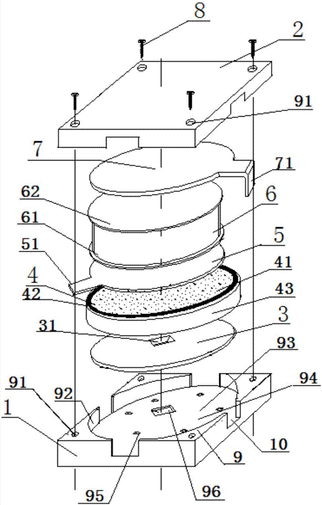
[0026] This embodiment provides a compound MOV with GDT added, such as figure 1 As shown, a lower case body 1 is provided with an upper case body 2, and a lower lead-out electrode 3 embedded in the lower case body 1 is also provided. On the lower lead-out electrode 3, MOV chips 4, middle lead-out Electrode 5, two-pole GDT6 (including lower discharge electrode 61 and upper discharge electrode 62), upper lead-out electrode 7; the upper box body 2 is covered on the upper lead-out electrode 7, and the lower The box body 1 is fastened as a whole, and the lower lead-out electrode 3 , the MOV chip 4 , the middle lead-out electrode 5 , the diode GDT 6 , and the upper lead-out electrode 7 are tightly pressed and fixed.

[0027] Wherein, the four corners of the upper box body 2 and the lower box body 1 are provided with bosses 9 (in figure 1 Among them, one is marked in the upper box body 2 and one in the lower box body 1, and the other same structures are not marked, and the same stru...

Embodiment 2

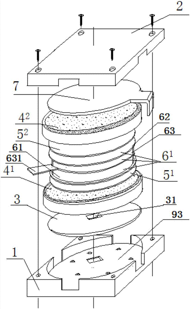
[0036] Such as image 3 As shown, the difference between this embodiment and Embodiment 1 lies in that the first MOV chip 4 is sequentially stacked on the lower lead-out electrode 3 1 , the first metal gasket 5 1 , three-pole GDT6 1 , the second metal gasket 5 2 , the second MOV chip 4 2 , The upper lead-out electrode 7, that is: replace the middle lead-out electrode 5 with a circular or rectangular metal gasket 5 1 and 5 2 , and the three-pole GDT6 1 A triode gas discharge tube comprising a lower discharge tube 61 and an upper discharge tube 62 with an intermediate electrode 63 is adopted, and the MOV chip 4 in Embodiment 1 is retained, named as the first MOV chip 4 in this embodiment 1 , and then add one of the first MOV chip 4 in the triode GDT61 and the upper lead-out electrode 7 1 same MOV chip, named as the second MOV chip 4 2 . At this time, the cylindrical accommodation space 93 composed of the lower box body 1 and the upper box body 2 accommodates the lower l...

Embodiment 3

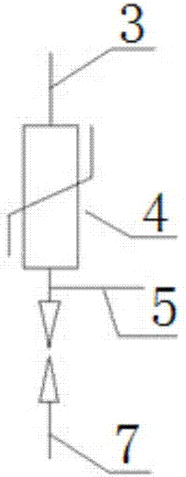
[0039] Such as Figure 5 As shown, the difference between this embodiment and Embodiment 1 is that: in the case where the contact surface between the MOV chip 4 and the bipolar GDT6 is flat, the middle lead-out electrode 5 can also be omitted, that is, the bottom lead-out electrode 5 can be omitted. The MOV chip 4 , the bipolar GDT 6 , and the upper lead-out electrode 7 are sequentially stacked on the electrode 3 . That is: the middle lead-out electrode 5 is removed, and the cylindrical accommodation space 93 composed of the lower box body 1 and the upper box body 2 accommodates the lower lead-out electrode 3, the MOV chip 4, the bipolar GDT6, and the upper lead-out electrode. Electrode 7. If the one provided by this embodiment is added to the composite MOV access circuit of GDT, because compared with embodiment 1, the middle lead-out electrode 5 is omitted, as Figure 6 shown.


PUM


Abstract

The present invention relates to the technical field of design of a varistor composite component, and specifically discloses a GDT (Gas discharge tube)-added composite MOV (Metal Oxide Varistor), the GDT-added composite MOV is provided with an upper box body and a lower box body, is also provided with a lower extraction electrode embedded in the lower box body, a MOV chip, a middle extraction electrode, a GDT and an upper extraction electrode are successively stacked on the lower extraction electrode, or the MOV chip, the GDT and the upper extraction electrode are successively stacked on the lower extraction electrode. The independent separated MOV and GDT are combined into an integrated structure, can improve the electrical performance requirements, meanwhile is miniaturized, and can meet higher requirements of an electronic circuit and a signal channel; due to the gap isolation effect of the GDT, the MOV chip can normally work without bearing a working voltage, semiconductor grain aging speed is very slow, no current is leaked during working, the service life is improved, a damp proof layer and an anti-side flash cover are arranged on the edge, and the GDT-added composite MOV has longer service life, higher reliability and stronger weathering resistance.

Description

technical field [0001] The invention relates to the technical field of design of piezoresistor composite components, in particular to a composite MOV added with GDT. Background technique [0002] Conventional MOV (Metal Oxide Varistor, zinc oxide resistor) has special nonlinear UI characteristics (ie, volt-ampere characteristics, U represents voltage, and I represents current). Interference, frequent power switch action, power system failure, etc., the voltage on the line suddenly increases to exceed the conduction voltage of the MOV, and the MOV will enter the conduction region. The nonlinear coefficient value between the current (I) and the voltage (U) ( Nonlinearity Parameter) can reach dozens or hundreds. At this time, the impedance of the MOV will be reduced to only a few ohms, so that the overvoltage will form a surge current and leak out to protect the connected electronic products or expensive components. [0003] With the rapid development of clean energy technolog...

Claims


Application Information

Patent Timeline
IPC IPC(8): H01C1/014H01C1/022H01C1/084H01C7/00H01C7/112H01C7/12
CPCH01C1/014H01C1/022H01C1/084H01C7/001H01C7/112H01C7/123
Inventor 曾清隆陈泽同
Owner LONGKE ELECTRONICS HUIYANG
Why Eureka
Try Eureka