
Power regulating method and device for light network unit, light communication system

An optical network unit and power adjustment technology, which is applied in the field of optical communication and can solve the problems of insufficient optical power budget and standard requirements.

Inactive Publication Date: 2017-11-10
ZTE CORP
View PDF0 Cites 1 Cited by
  • Summary
  • Abstract
  • Description
  • Claims
  • Application Information

AI Technical Summary

Problems solved by technology

[0005] The present invention provides a power adjustment method and device for an optical network unit, and an optical communication system to solve the problem that the optical power budget is insufficient to meet the standard requirements caused by using the existing optical power adjustment mechanism in the NGPON2 system

Method used


Image

  • Power regulating method and device for light network unit, light communication system
  • Power regulating method and device for light network unit, light communication system
  • Power regulating method and device for light network unit, light communication system

Examples


no. 1 example

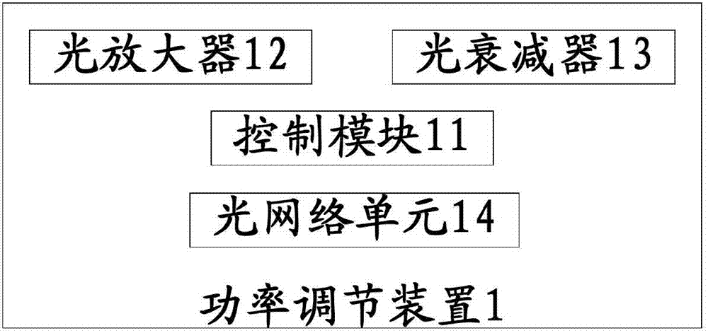
[0038] figure 1It is a schematic structural diagram of the power regulating device provided by the first embodiment of the present invention, which is represented by figure 1 It can be seen that in this embodiment, the power adjustment device 1 provided by the present invention includes: a control module 11, an optical amplifier 12, and an optical attenuator 13, and also includes an optical network unit 14 for outputting emitted light, wherein,

[0039] The control module 11 is configured to receive an adjustment instruction from the optical network unit 14, and control the optical amplifier 12 and the optical attenuator 13 to work according to the adjustment instruction;

[0040] The optical amplifier 12 is used to amplify the optical power of the emitted light of the optical network unit 14 under the control of the control module 11, and the optical amplifier 12 performs non-similar amplification on the signal light and crosstalk light in the emitted light;

[0041] The opt...

no. 2 example

[0051] figure 2 The flow chart of the power adjustment method provided by the second embodiment of the present invention is composed of figure 2 It can be seen that in this embodiment, the power adjustment method provided by the present invention includes the following steps:

[0052] S201: the control module receives an adjustment instruction from the optical network unit, and controls the operation of the optical amplifier and the optical attenuator according to the adjustment instruction;

[0053] S202: Under the control of the control module, the optical amplifier amplifies the optical power of the transmitted light of the optical network unit, and the optical amplifier performs non-similar amplification on the signal light and crosstalk light in the transmitted light;

[0054] S203: Under the control of the control module, the optical attenuator attenuates the optical power of the emitted light of the optical network unit, and the optical attenuator attenuates the sign...

no. 3 example

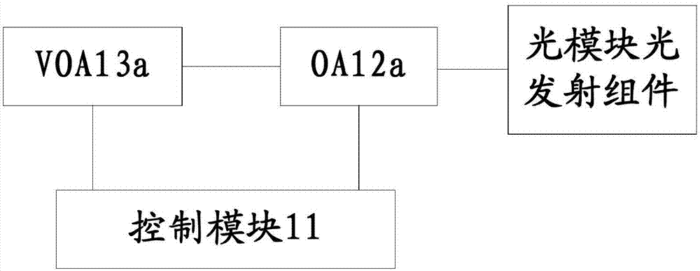
[0069] Such as image 3 As shown, the ONU power adjustment device is placed outside the optical transmission component of the optical module in a discrete form. In the figure, OA (Optical Amplifier) ​​is an optical amplifier, and VOA (Variable Optical Attenuator) is a variable optical attenuator. In the figure, the control module 11 is connected to OA12a and VOA13a at the same time. Preferably, the optical module optical emission component is connected to the optical amplifier OA12a of the power adjustment device, and the optical emission component of the optical network unit can also be connected to the optical attenuator VOA13a of the power adjustment device. , OA12a and VOA13a may use independent devices to implement corresponding functions.


PUM


Abstract

The invention provides a power regulating method and device for a light network unit, and a light communication system. The method comprises the following steps: a control module receives a regulating instruction of an light network unit and controls the work of the light amplifier and an light attenuator according to the regulating instruction; an light amplifier performs the light power amplification on the transmitting light of the light network unit under the control of the control module; the light amplifier performs the non-same-level amplification on the signal light and crosstalk light in the transmitting light; the light attenuator performs the light power attenuation on the transmitting light of the light network unit under the control of the control module; the light attenuator performs the same-level attenuation on the signal light and the crosstalk light in the transmitting light. By using the power regulating method provided by the invention, the transmitting light power of the ONU is attenuated by using the light attenuator, the crosstalk influence can be effectively relieved, the transmitting light power of the ONU is amplified by using the light amplifier, thereby enabling the transmitting light power of the ONU to satisfy the requirement of the NGPON2 standard.

Description

technical field [0001] The invention relates to the field of optical communication, in particular to a power adjustment method and device for an optical network unit, and an optical communication system. Background technique [0002] With the diversification of client services, such as the popularity of high-definition network TV, cloud storage cloud computing, social networking, video sharing, etc., the number of users of operators' broadband access networks is increasing day by day, and the demand for access bandwidth of users is also increasing rapidly , GPON and 10GPON passive optical networks need to move towards NG-PON2 (Next-Generation Passive Optical Network Stage 2, next-generation passive optical network stage 2, which has larger capacity, wider coverage, lower unit bandwidth cost, more convenient operation and The second stage of source optical access network) evolution. In order to develop a more advanced optical access network, the FSAN (Full Service Access Net...

Claims


Application Information

Patent Timeline
IPC IPC(8): H04B10/293H04B10/564
CPCH04B10/00H04B10/2939H04B10/564
Inventor 那婷
Owner ZTE CORP
Learn More