Electric spindle angular contact ball bearing pre-tightening force regulating mechanism

An angular contact ball bearing and preload adjustment technology, which is applied to metal processing machinery parts, large fixed members, metal processing equipment, etc., can solve uncontrollable problems, ensure processing quality, improve processing accuracy and processing efficiency, Effect of reducing vibration and noise

Active Publication Date: 2017-11-14
SHENYANG JIANZHU UNIVERSITY
View PDF8 Cites 10 Cited by
  • Summary
  • Abstract
  • Description
  • Claims
  • Application Information

AI Technical Summary

Problems solved by technology

However, the current preload of the electric spindle is uncontrollable in use. In order to ensure that the electric spindle can adjust its bearing preload from time to time when it is working, it has high reliability under high and low speeds and light and heavy loads. The present invention designs an automatic adjustment mechanism for the pretightening force of the electric spindle bearing

Method used


Image

  • Electric spindle angular contact ball bearing pre-tightening force regulating mechanism

Examples


Embodiment Construction

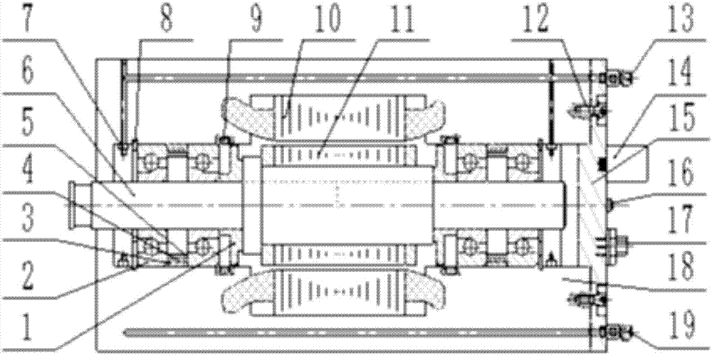
[0032] Such as figure 1 An electric spindle angular contact ball bearing pre-tightening force adjustment mechanism is shown, including an oil baffle ring 1, an angular contact ball bearing 2, a three-layer sleeve, a main shaft 6, an oil injection nozzle 7, a hole elastic retaining ring 8, a non-contact Type temperature sensor 9, stator coil 10, mover coil 11, hexagon socket screw 12, oil nozzle 13, piezoelectric ceramic drive power 14, end cover 15, angular acceleration vibration sensor 16, connector 17, electric spindle housing 18 And water junction 19;

[0033] The mover coil 11 is sleeved on the main shaft 6, the stator coil 10 is installed in the electric spindle housing 18, the main shaft is arranged in the electric spindle housing 18, and the mover coil 11 and the stator coil 10 are There is an air gap between;

[0034] Sleeve the oil baffle ring 1 on both ends of the mover coil 11 on the main shaft 6;

[0035] A pair of angular contact ball bearings 2 are respectively provi...


PUM


Abstract

The invention exposes an electric spindle angular contact ball bearing pre-tightening force regulating mechanism. An elastic check ring for a hole, angular contact ball bearings and an oil stopping ring are sequentially arranged on a spindle in a sleeving manner; three layers of sleeves are installed between the bearings installed in pairs; a non-contact type temperature sensor is installed between the bearings and the oil stopping ring; an angular acceleration vibration sensor is installed at the tail end of the electric spindle; and an oil spraying nozzle is installed on the face of the outer side of the bearings. A piezoelectric ceramic driving power source, a connector assembly, an oil receiving nozzle and a water receiving nozzle are installed on an end cover on the tail portion of the electric spindle. The piezoelectric ceramic driving power source is connected with two annularly stacked piezoelectric ceramic sleeves through a circuit. According to the technical scheme, by means of a good automatic pre-tightening force regulating technology, the pre-tightening force of the electric spindle bearings is effectively regulated, the electric spindle temperature rise is regulated and controlled, noise is lowed, the supporting precision and the rotating precision of the bearings are improved, the service life of the bearings is prolonged, and therefore the dynamic performance of the electric spindle is improved, and the machining precision and the work efficiency of a machine tool adopting an electric spindle unit are improved.

Description

Technical field [0001] The invention relates to an electric spindle rotor angular contact ball bearing pre-tightening force adjustment mechanism, in particular to an automatic, new, accurate and dynamic feedback pre-tightening force adjustment mechanism. Background technique [0002] Electric spindle is a new technology that integrates machine tool spindle and spindle motor in the field of CNC machine tools. The main drive system of the high-speed CNC machine tool cancels the pulley drive and gear drive. The main shaft of the machine tool is directly driven by the built-in motor, thus shortening the length of the main transmission chain of the machine tool to zero, realizing the "zero transmission" of the machine tool. The electric spindle has the advantages of compact structure, light weight, low inertia, low noise, fast response, etc. It also has high speed and high power, simplifies machine tool design, and is easy to realize spindle positioning. It is an ideal structure in h...

Claims


Application Information

Patent Timeline
Patent Type & Authority Applications(China)
IPC IPC(8): B23B19/02
CPCB23Q1/70
Inventor 张珂安爱博王子男白晓天
Owner SHENYANG JIANZHU UNIVERSITY
Why Eureka
Try Eureka