Battery pack

A technology for battery packs and battery cells, applied to battery pack components, circuits, electrical components, etc., can solve the problems of lack of safety protection structure, unstable battery pack structure, etc., and achieve the effect of reducing or eliminating expansion or compression deformation

Pending Publication Date: 2017-11-14
ANHUI GIANT BATTERY TECH CO LTD
View PDF12 Cites 0 Cited by
  • Summary
  • Abstract
  • Description
  • Claims
  • Application Information

AI Technical Summary

Problems solved by technology

[0005] In view of this, the embodiment of the present invention provides a battery pack structure, which can solve the technical problem in the prior art bipolar battery structure that the battery pack structure is unstable due to the lack of a safety protection structure

Method used


Image

  • Battery pack
  • Battery pack
  • Battery pack

Examples


Embodiment 1

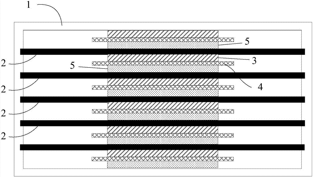
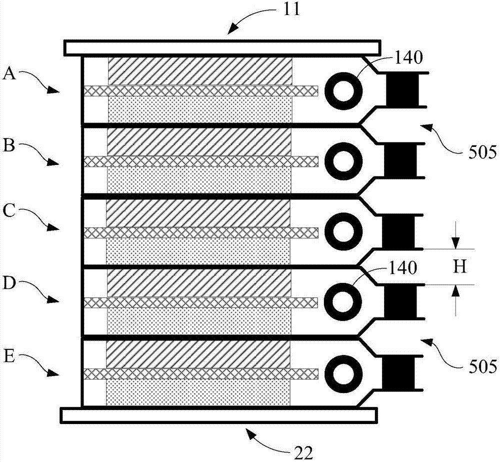
[0038] see figure 2 , figure 2 It is a structural schematic diagram of the first embodiment of the battery pack of the present invention; the battery pack in this embodiment includes 5 battery cells (A, B, C, D, E), of course, in other embodiments, the number of battery cells is not the same as Not limited to 5, can be 2, 3, 4, 6... or more. The exact number depends on the output voltage requirements of the battery. Multiple battery cells connected in series can form a battery pack with a specified output voltage.

[0039] The outside of the battery pack is the upper and lower end plates (11, 22), and the upper and lower end plates (11, 22) can be metal collector plates, which function to conduct electricity and provide external support, so they need to be conductive and have Certain mechanical strength. In addition, the upper and lower end plates (11, 22) can also be support plates for forming the casing of the battery pack. The upper and lower end plates (11, 22) can ...

Embodiment 2

[0051] It should be noted that in the subsequent embodiments, only the structural differences from the first embodiment will be emphasized, and the same or similar structural features will not be described in detail.

[0052] see Figure 4 , Figure 4 It is a structural schematic diagram of the second embodiment of the battery pack of the present invention. The battery pack in this embodiment also includes 5 battery cells A, B, C, D, and E. The difference from the previous embodiment is that in this embodiment Both ends of the metal plate of the battery cell are provided with separation areas, and a seal is provided between the separation areas of the two metal plates of the same battery cell. This structure can form more gaps 505 between the separation areas, thus further improving the Compared with the structure in Example 1, the expansion resistance coefficient of the battery cell is doubled. In addition, an elastic buffer 140 is added to further enhance the expansion res...

Embodiment 3

[0056] see Figure 8 , Figure 8 It is a structural schematic diagram of the third embodiment of the battery pack of the present invention. Compared with Embodiment 1, in this embodiment, an elastic support body 506 is provided between the adjacent metal plates of adjacent battery cells at the same end separation area, which is equivalent to Since the elastic support body fills the original gap 505 , the elasticity of the elastic support body 506 can enhance the extensibility of the stacking direction of the battery pack. Any suitable material can be used for the elastic support body 506 . For example, materials such as silicone rubber, EPDM rubber, polyethylene, and polyvinyl chloride have the following characteristics: good insulation, can coexist with electrolytes, and can be stable at voltages below 10 volts and below 200 degrees. Preferably, the elastic support body can increase the elastic deformation by at least 15% or more in the stacking direction of the battery cel...


PUM


Abstract

The invention provides a battery pack, which comprises at least two battery units, wherein the at least two battery units are arranged in a stacking manner; shells of the battery units comprise upper metal plates and lower metal plates; sealing members are arranged between the upper metal plates and the lower metal plates; the metal plates of the adjacent battery units are partially connected together in an electric conduction manner; connecting areas of the sealed metal plates of the adjacent battery units are of corrugated structures; multiple gaps are formed among the corrugated structures. In comparison with the prior art, according to the battery pack provided by the invention, through arranging the corrugated structures in the connecting areas between the adjacent battery units, the multiple gaps are formed among the corrugated structures; further, safety protection structures of the battery units are constituted; the harm brought as the battery units swell or are pressed to deform can be effectively decreased or eliminated.

Description

technical field [0001] The invention belongs to the technical field of battery manufacturing, and in particular relates to a battery pack. Background technique [0002] At present, in the structural design of fuel cells, the bipolar battery structure is a common design method, and bipolar batteries can be used to improve battery energy storage capacity based on weight and volume, reduce package weight and volume, and provide stable battery performance and low internal resistance. [0003] The structure of a bipolar battery generally includes an electrically conductive bipolar layer, a so-called bipolar plate, which serves as an electrical interconnection between adjacent cells in the battery and as a partition between individual battery cells. To successfully utilize the bipolar structure, the bipolar plates need to be sufficiently conductive to transfer current from one cell to the other and have good chemical stability in the battery environment. [0004] see figure 1 ,...

Claims


Application Information

Patent Timeline
IPC IPC(8): H01M2/02H01M50/10
CPCY02E60/10H01M50/204
Inventor 孙尚传
Owner ANHUI GIANT BATTERY TECH CO LTD
Why Eureka
Try Eureka