
Weld electrode, method for resistance spot welding, and automobile

A welding electrode and electrode technology, which is applied in the direction of welding/welding/cutting items, welding equipment, electrode characteristics, etc., can solve problems such as corrosion, uneven impedance distribution, etc., achieve the effect of low corrosion risk and ensure detectability

Inactive Publication Date: 2017-11-17
VOLKSWAGEN AG
View PDF10 Cites 0 Cited by
  • Summary
  • Abstract
  • Description
  • Claims
  • Application Information

AI Technical Summary

Problems solved by technology

[0016] The electrodes known from these documents for resistance spot welding have in common that they are constructed of a copper material, especially in the border region of the contact surfaces, for contacting the workpiece to be welded, which copper material is formed in the described inhomogeneous The introduction of force has the disadvantage that an inhomogeneous impedance distribution and thus a temperature gradient in the electrode and at the material can lead to a localized melting of the electrode material and / or the material in the area of ​​contact, so that An undesired welding process occurs between the electrode and the material, which, when the electrode is removed, also leads to the retention of copper particles on the workpiece and to the formation of corrosion associated therewith

Method used


Image

  • Weld electrode, method for resistance spot welding, and automobile
  • Weld electrode, method for resistance spot welding, and automobile
  • Weld electrode, method for resistance spot welding, and automobile

Examples


Embodiment Construction

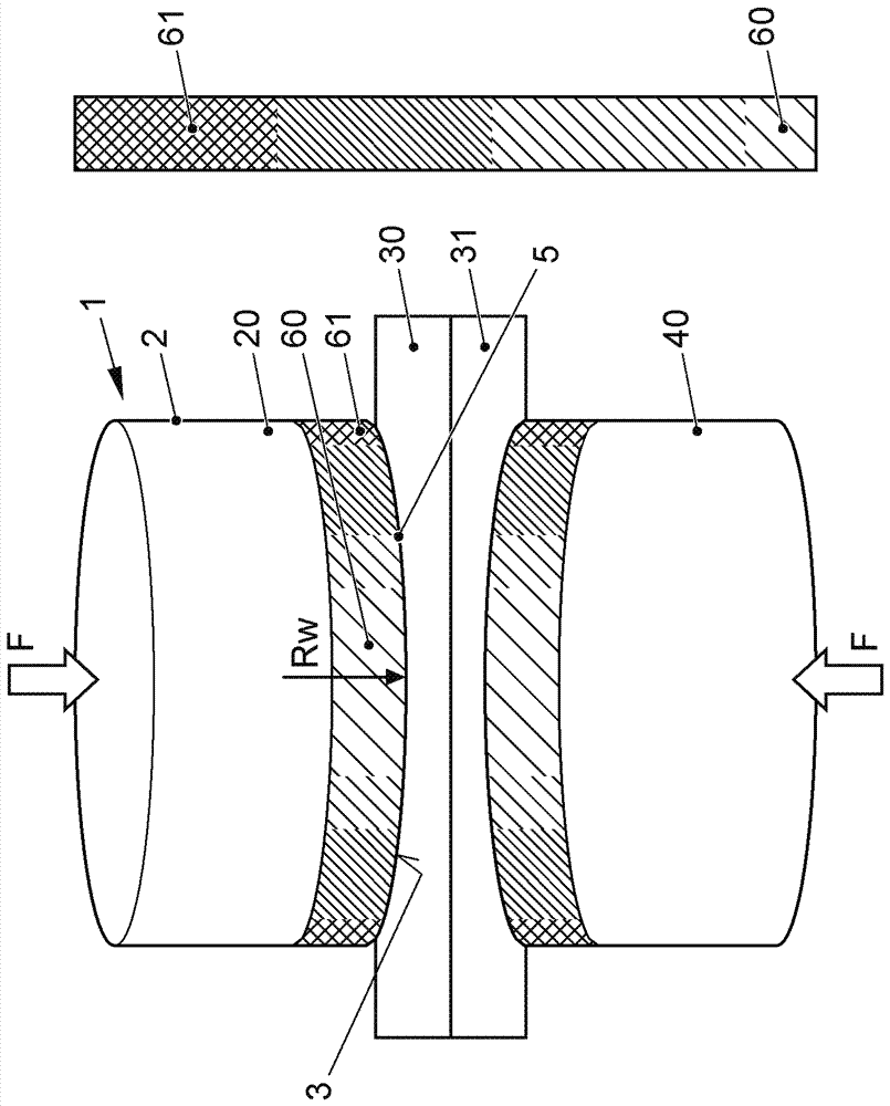
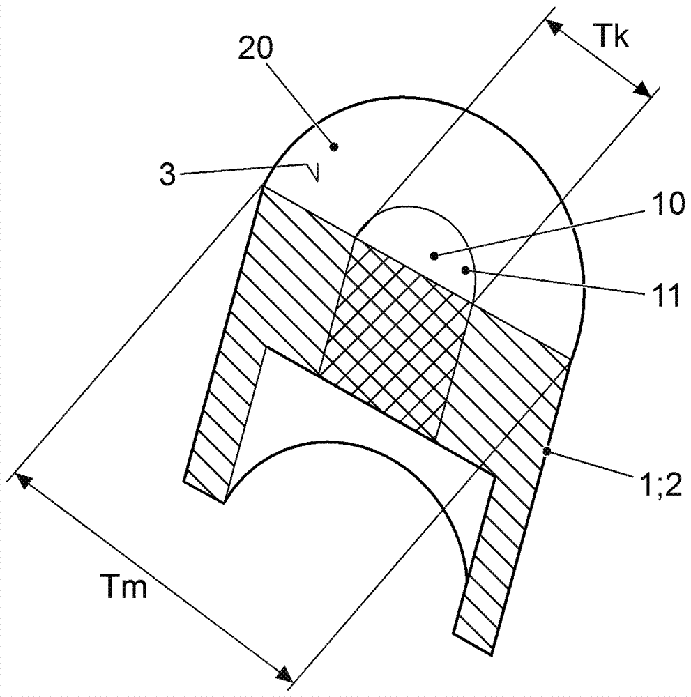
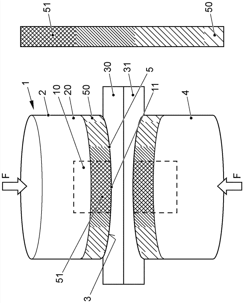
[0065] exist figure 2 A welding electrode according to the invention for resistance spot welding is presented in , which is here shown in perspective in cross-section. The electrode rod 1 can be seen, which is substantially designed as a cylinder. The outer side 2 of the electrode shaft 1 is formed by an electrode sheath 20 which essentially has a tubular shape or defines a ring shape in cross-section. The electrode core 10 is located in the volume enclosed by the electrode sheath 20 . According to the invention the electrode sheath is made of a material with a hot hardness of at least 600°C.

[0066] The electrode core is preferably made of a material with a conductivity of at least 85% IACS, if possible even 100% IACS. This means that the electrode core has at least 49.3×10 6 S / m or even at least 58×10 6 S / m conductivity.

[0067] It is clear that the end-side end 11 of the electrode core 10 forms part of the end face 3 of the electrode rod 1 , ie the central region. ...


PUM

PropertyMeasurementUnit
Hardnessaaaaaaaaaa

Abstract

The invention relates to a weld electrode, which used for resistance spot welding, a method for resistance spot welding of a workpiece, and an automobile. The weld electrode is used for resistance spot welding and includes an electrode pole (1) which has an end surface (3) that is pressed to the to-be-welded workpiece and introduces current into the workpiece. An electrode core (10) is at least formed at the end surface (3) and an electrode sheath (20) basically covers the electrode core (10) and forms the outer side (2) of the electrode pole (1). An end portion (11) of the electrode core (10) configures the area of the end surface (3) of the electrode pole (1). The electrode sheath (20) is prepared from a material which is at least 400 N / mm<2> in tensile strength.

Description

technical field [0001] The invention relates to a welding electrode for resistance spot welding (widersstandspunktschweißen, sometimes referred to as resistance spot welding) and a method for resistance spot welding of workpieces, in particular body parts. Furthermore, the invention relates to a motor vehicle having a component group whose components are connected using the method according to the invention for resistance spot welding. Background technique [0002] It is a known problem that electrodes for resistance spot welding are subject to relatively high wear or require relatively high reworking effort. This relates in particular to welding electrodes for welding strongly oxidizing materials, such as aluminum or magnesium sheet parts. The lifetime of resistance spot welding electrodes for welding aluminum or magnesium sheet parts is reduced by up to 90% compared to resistance spot welding of steel materials. Correspondingly, increased effort can be incurred in reproc...

Claims


Application Information

Patent Timeline
IPC IPC(8): B23K11/31B23K11/30B23K11/11
CPCB23K11/185B23K11/115B23K35/0205B23K35/302B23K2103/10B23K2103/15B23K11/314B23K11/11B23K11/30
Inventor M.图赫特费尔德
Owner VOLKSWAGEN AG
Learn More