Ball screw of engraving-milling machine

A ball screw, engraving and milling machine technology, applied in the direction of metal processing machinery parts, metal processing, metal processing equipment, etc., can solve the problem that the ball screw does not have cleaning and dust, achieve high reversibility, high efficiency, and improve precision and quality, novel effect of structure

Pending Publication Date: 2017-11-17
ZHEJIANG TIEZHENG MACHINERY CO LTD
View PDF8 Cites 0 Cited by
  • Summary
  • Abstract
  • Description
  • Claims
  • Application Information

AI Technical Summary

Problems solved by technology

[0003] The technical problem to be solved by the invention is to overcome the problem that the existing ball screw does not have the function of cleaning and dust, and to provide a ball screw for engraving and milling machine

Method used


Image

  • Ball screw of engraving-milling machine
  • Ball screw of engraving-milling machine
  • Ball screw of engraving-milling machine

Examples


Embodiment 1

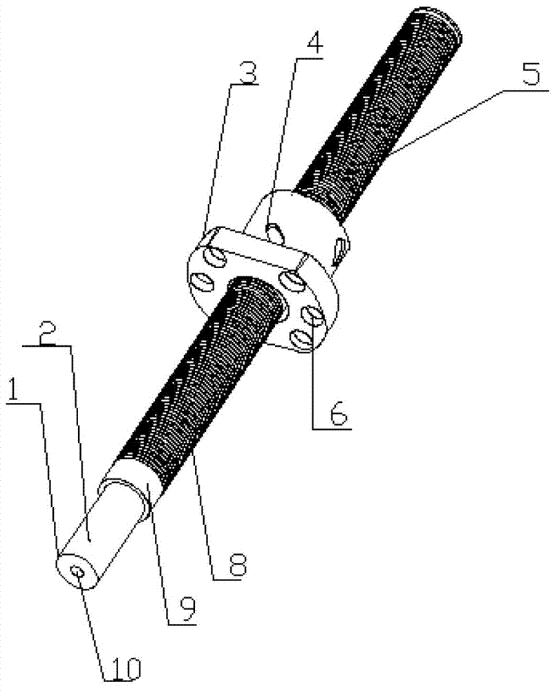
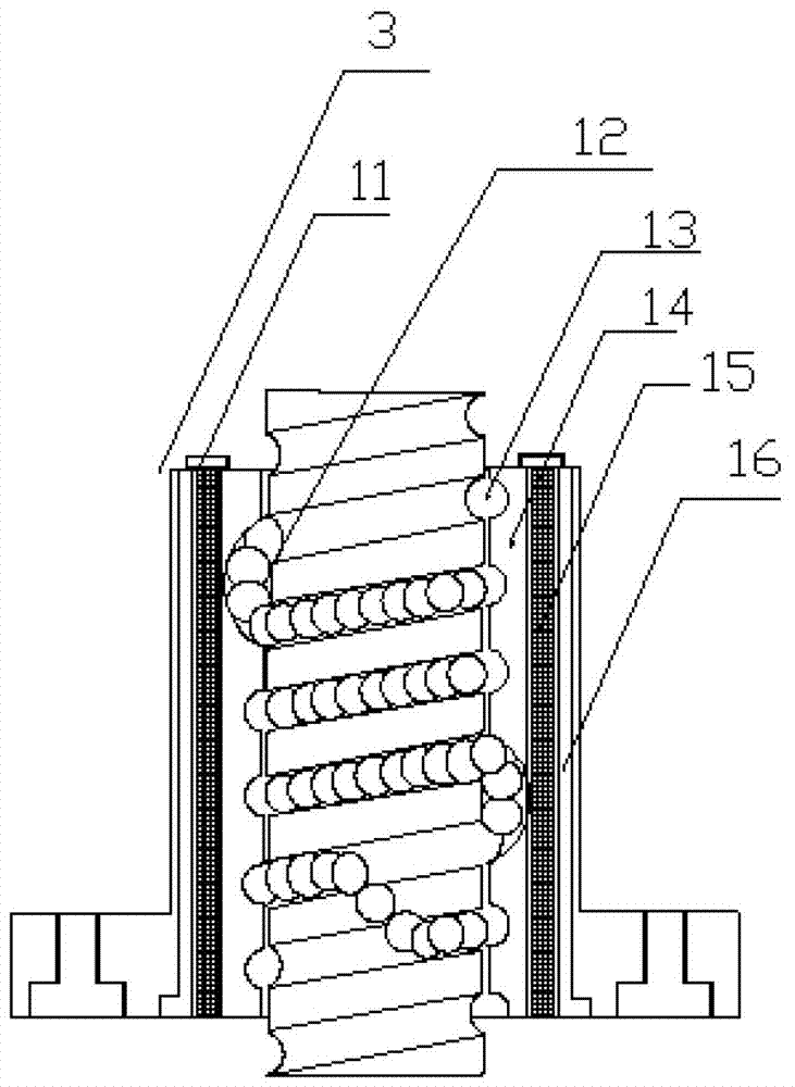
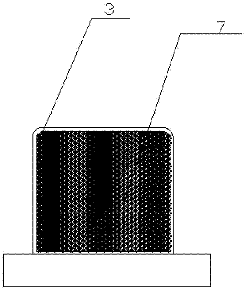
[0019] Such as Figure 1-3 As shown, the present invention provides a ball screw for engraving and milling machine, the rod body 1 is provided with a threaded rod 5, one end of the threaded rod 5 is provided with a shaft sleeve installation position 9, and one end of the shaft sleeve installation position 9 is provided with a processing shaft end 2, A screw hole 10 is provided on the processing shaft end 2, a threaded structure 8 is provided on the surface of the threaded rod 5, a nut 3 is provided on the threaded rod 5, a reverser 4 is provided on the nut 3, and one end of the nut 3 is provided with The countersunk hole 6 is installed on the flange, and the inside of the nut 3 is provided with a groove 13, one end of the groove 13 is provided with an inner wall 14, one end of the inner wall 14 is provided with an electrostatic sheet 15, and the top of the electrostatic sheet 15 is provided with a clamping shaft 11, One end of the electrostatic sheet 15 is provided with a holl...


PUM


Abstract

The invention discloses a ball screw of an engraving-milling machine. A thread rod is arranged on a screw body; a shaft sleeve installation position is formed at one end of the thread rod; a machining shaft end is arranged at one end of the shaft sleeve installation position; a screw hole is formed in the machining shaft end; a thread structure is arranged on a surface layer of the thread rod; a nut is arranged on the thread rod; a reverser is arranged on the nut; a flange installation counterbore hole is formed in one end of the nut; a groove is formed in the nut; an inner wall is arranged at one end of the groove; an electrostatic sheet is arranged at one end of the inner wall; a clamping shaft is arranged at a top end of the electrostatic sheet; a hollow layer is arranged at one end of the electrostatic sheet; a plurality of dust absorption holes are formed in a surface layer of the nut; and a ball is arranged between the thread rod and the groove. The ball screw disclosed by the invention is novel in structure, and simple and convenient to operate, and has the characteristics of being high in accuracy, reversible and high in efficiency; the electrostatic sheet and the hollow layer facilitate absorption for dust falling off during working of the engraving-milling machine through the dust absorption holes; and extremely high dustproof efficiency is achieved, and improvement for working precision and quality is benefited.

Description

technical field [0001] The invention relates to a ball screw, in particular to a ball screw of an engraving and milling machine. Background technique [0002] At present, engraving and milling machine (CNC engraving and milling machine) is a kind of CNC machine tool. It is generally considered that the engraving and milling machine is a CNC milling machine that uses small tools, high power, and high-speed spindle motors. The advantage of engraving machine is engraving. If the hardness of the processed material is relatively high, it will appear powerless. The emergence of engraving and milling machines can be said to fill the gap between the two. The engraving and milling machine can not only engrave, but also mill. It is a high-efficiency and high-precision CNC machine tool. The concept of engraving and milling machine was first proposed and realized by Jiatie. The engraving and milling machine has a wide range of applications, and is widely used in the rough and fine m...

Claims


Application Information

Patent Timeline
Patent Type & Authority Applications(China)
IPC IPC(8): B23Q5/40B23Q5/54
CPCB23Q5/40B23Q5/54
Inventor 戴永海
Owner ZHEJIANG TIEZHENG MACHINERY CO LTD
Why Eureka
Try Eureka