Eureka AIR delivers breakthrough ideas for toughest innovation challenges, trusted by R&D personnel around the world.

Electric coupler pulling-out force testing device and method thereof

An electrical connector and testing device technology, which is applied in the direction of accumulator device, fluid pressure actuating device, measuring device, etc., can solve the problem that the connector pull-off force testing device does not involve water pressure environment and cannot test underwater connectors. Transient pull-off force, inability to meet the actual working conditions of pull-off force, etc., to achieve the effect of strong human-computer interaction ability, friendly interface, and large stepless speed regulation range

Active Publication Date: 2017-11-17
杭州华泰电液成套技术有限公司
View PDF6 Cites 7 Cited by
  • Summary
  • Abstract
  • Description
  • Claims
  • Application Information

AI Technical Summary

Problems solved by technology

[0007] 1. The domestic connector pull-off force test device does not involve the water pressure environment, and is not suitable for underwater electrical connector testing;
[0008] 2. Domestic pull tests are mostly static load tests. Only a few test devices involve pull-off at a certain speed, but the test speed range is small. However, the pull-off speed has a greater impact on the pull-off force. Occasions with a high take-off speed cannot meet the test requirements;
[0009] 3. The domestic pull-off force test device can measure the pull-off force of the connector within 2500N, which cannot meet the actual working conditions with large pull-off force;
[0010] 4. Foreign underwater connector testing devices cannot test the transient pull-off force of underwater connectors. On the one hand, the transient pull-off force index can judge the reliability of the electrical connector connection. , which has guiding significance for calculating the pulling force exerted by the electrical connector;
[0011] 5. The speed adjustment is manual adjustment, and the degree of automation is low

Method used


Image

  • Electric coupler pulling-out force testing device and method thereof
  • Electric coupler pulling-out force testing device and method thereof
  • Electric coupler pulling-out force testing device and method thereof

Examples


Embodiment Construction

[0028] The present invention will be further described below in conjunction with embodiment and accompanying drawing.

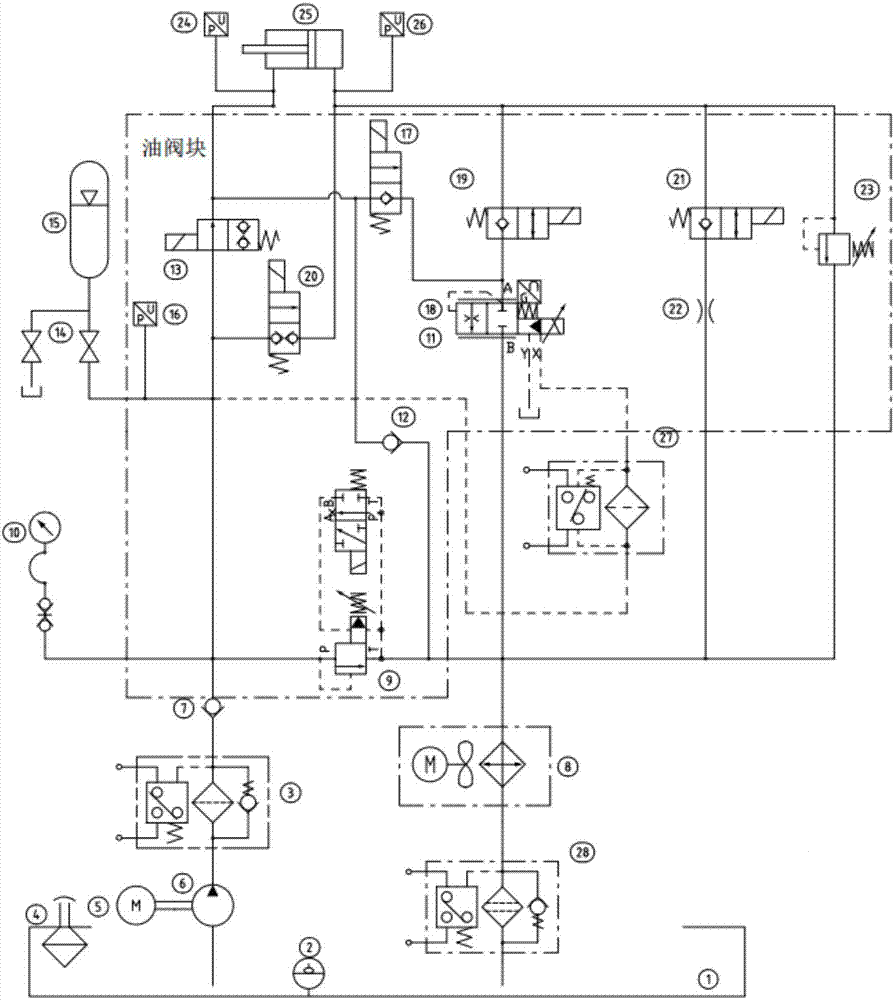
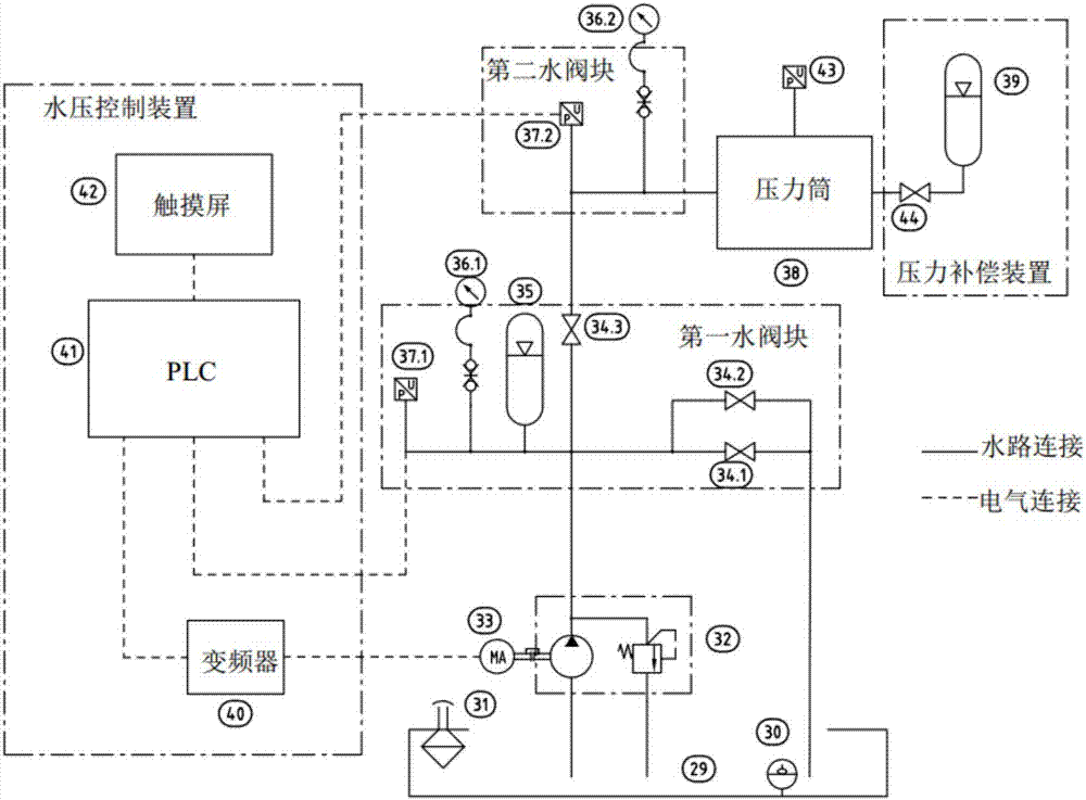
[0029] Such as figure 1 Described is the principle diagram of the hydraulic system of the example of the present invention. Among them, the pilot relief valve 9, the second check valve 12, the first electromagnetic reversing valve 13, the second electromagnetic reversing valve 17, the proportional throttle valve 18, the third electromagnetic reversing valve 19, the fourth electromagnetic reversing valve The valve 20, the fifth electromagnetic reversing valve 21 and the safety valve 23 are installed on the oil valve block. The oil tank 1 has the function of storing oil and providing the system with original parts to be placed and fixed. The fuel tank liquid level thermometer 2 displays the oil temperature and liquid level in the fuel tank. The first high-pressure filter 3, the second high-pressure filter 27, and the oil return filter 28 filter the oil to pr...


PUM


Abstract

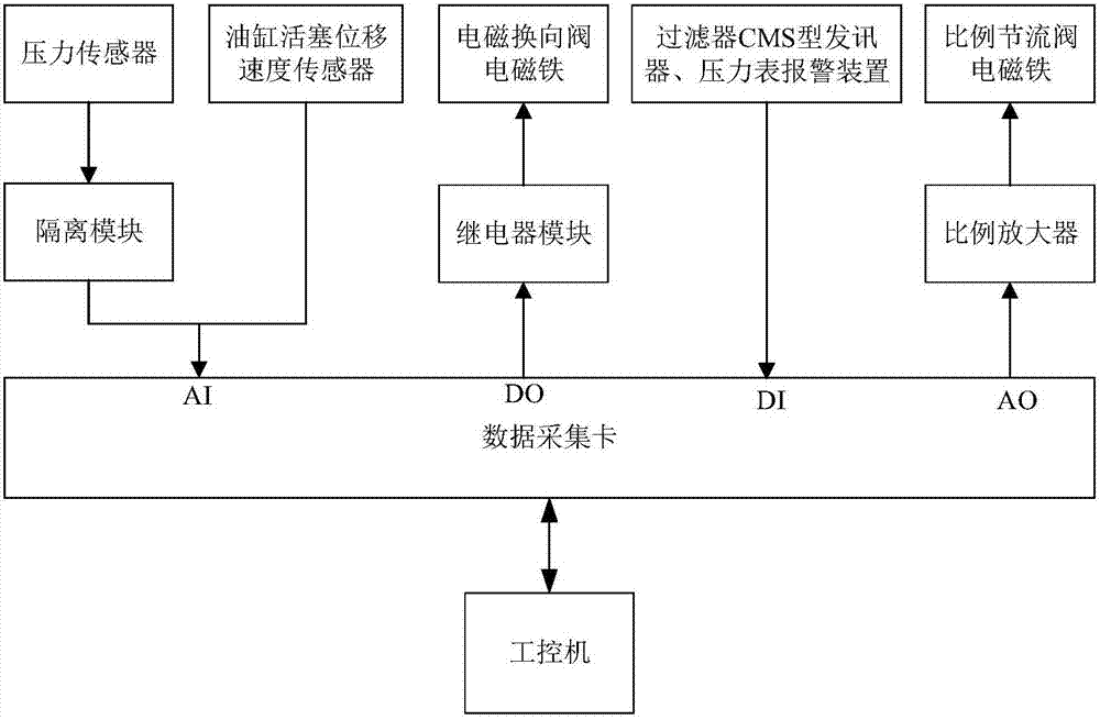
The invention provides an electric coupler pulling-out force testing device and a method thereof. The electric coupler pulling-out force testing device is composed of a hydraulic system, a water pressure control system and a measurement and control system. The hydraulic system is composed of a gear pump, solenoid directional valves, a pilot overflow valve, an energy accumulator, a proportional throttle valve, an oil cylinder, an air cooler, filters and a pressure gage. The water pressure control system is composed of a pressure testing pump, a variable frequency motor, stop valves, energy accumulators, pressure gages, pressure sensors, a pressure barrel, a motor frequency converter, a PLC and a touch screen. The measurement and control system is composed of pressure sensors, a displacement sensor, an industrial personal computer, a data acquisition card, a relay module and an isolation module. According to the testing device, a water pressure environment with the pressure ranging from 0 MPa to 6 MPa is built for electric coupler pulling-out, it is guaranteed that the pressure fluctuation range is within 5% in the electric coupler pulling-out process, the pulling-out speed within the range from 0 m / s to 1 m / s and the maximum pulling-out force not smaller than 5,000 N are provided, and the pulling-out force at the moment of electric coupler disengagement is calculated out.

Description

technical field [0001] The invention relates to an electric connector pull-off force test device and a method thereof, and belongs to the technical field of hydraulic control test systems. Background technique [0002] Underwater connectors are indispensable electronic components in marine and other underwater engineering and weaponry systems. Under the continuous application of electrical equipment. At present, with the development of offshore oil and the continuous development of weapon combat systems to deep sea areas, underwater connectors are more useful. Taking offshore oil development as an example, from 2013 to 2017, the investment in deep-water oil development will account for more than 50% of the total investment in offshore oil and gas development. Major oil companies have turned their attention to the deep-sea field where the level of development and exploration is still very low, prompting This has led to the increasing attention of underwater connectors and t...

Claims


Application Information

Patent Timeline
IPC IPC(8): F15B11/04F15B11/028F15B19/00F15B1/02F15B20/00F15B21/00F15B21/08G01M13/00
CPCF15B1/021F15B11/028F15B11/04F15B19/00F15B20/007F15B21/006F15B21/08F15B2211/20515F15B2211/7052F15B2211/857F15B2211/87G01M13/00
Inventor 张超靳晓阳付凯
Owner 杭州华泰电液成套技术有限公司
Why Eureka
Eureka Blog
Learn More