
Air Conditioning Waste Heat Collector Water Supply System

A water supply system, waste heat technology, applied in air conditioning systems, residential hot water supply systems, ventilation systems, etc., can solve problems such as electricity consumption and heat waste, and achieve the effects of improving efficiency, maintaining temperature and reducing transmission.

Active Publication Date: 2019-04-02
庞淮升
View PDF8 Cites 0 Cited by
  • Summary
  • Abstract
  • Description
  • Claims
  • Application Information

AI Technical Summary

Problems solved by technology

Among them, the condenser is a device that releases heat, that is, the heat absorbed in the evaporator and the heat converted by the compressor's work are transferred to the cooling medium to take away, and the cooling medium takes this part of heat away by consuming water pumps and fans. Power etc. are discharged into the atmosphere, which not only causes waste of heat, but also consumes extra electricity.

Method used


Image

  • Air Conditioning Waste Heat Collector Water Supply System
  • Air Conditioning Waste Heat Collector Water Supply System
  • Air Conditioning Waste Heat Collector Water Supply System

Examples


Embodiment Construction

[0028] The present invention will be further described in detail below in conjunction with the accompanying drawings and embodiments, so that those skilled in the art can implement it with reference to the description.

[0029] It should be understood that terms such as "having", "comprising" and "including" as used herein do not entail the presence or addition of one or more other elements or combinations thereof. It should be noted that the experimental methods described in the following embodiments, unless otherwise specified, are conventional methods, and the reagents and materials, if not otherwise specified, can be obtained from commercial sources; in the description of the present invention, The terms "transverse", "longitudinal", "axial", "radial", "upper", "lower", "front", "rear", "left", "right", "vertical", "horizontal ", "Top", "Bottom", "Inner", "Outer" and other indicated orientations or positional relationships are based on the orientations or positional relati...


PUM


Abstract

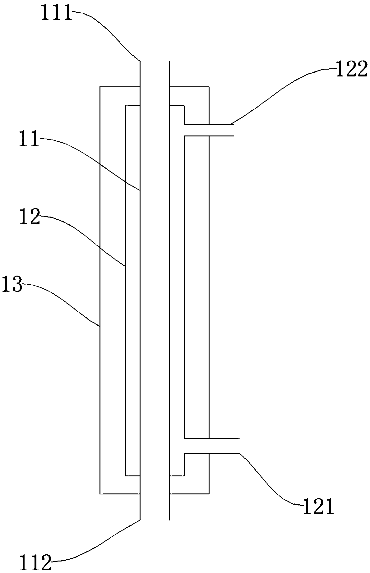
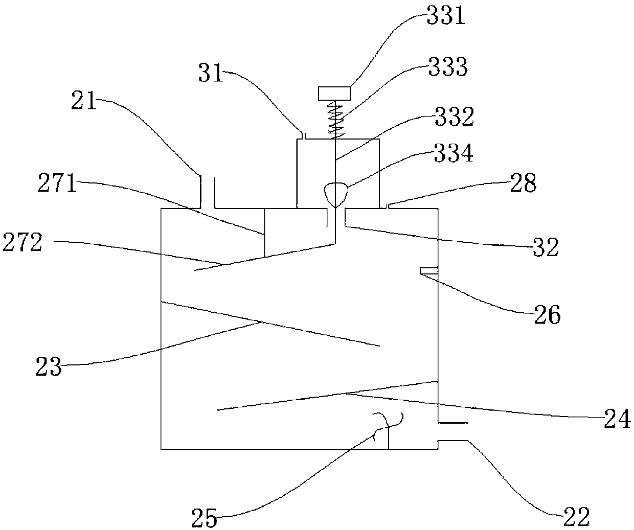
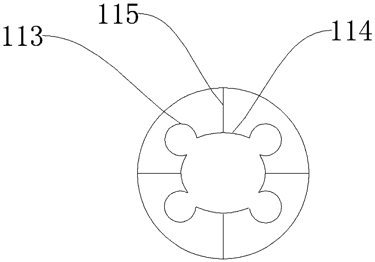
The invention discloses an air conditioner waste heat collection and water supply system. The air conditioner waste heat collection and water supply system comprises a heat exchanger, a water storage tank and a liquid storage box, wherein the heat exchanger is arranged between an air conditioner compressor and an air conditioner condenser, and the heat exchanger sequentially comprises a first sleeve, a second sleeve and a third sleeve from inside to outside. A third water inlet and a flowing liquid hole are oppositely formed in the top of the water storage tank, and a third water outlet is formed in the side wall, close to the bottom, of the water storage tank. A flowing liquid component, a first partition, a second partition, a worm wheel and a water level sensor are arranged in the water storage tank. The liquid storage box is arranged on the top of the water storage tank. The liquid storage box comprises a liquid injection hole formed in the top, a flowing liquid pipe which is arranged at the bottom and penetrates the flowing liquid hole and a gravity press assembly penetrating a liquid storage box body. The gravity press assembly comprises a gravity block, a connecting rod, a spring and a plug body. When water stops flowing into the third water inlet, the gravity block compresses the connecting rod to move downwardly so as to drive the plug body to be plugged into the flowing liquid pipe. By the adoption of the air conditioner waste heat collection and water supply system, waste heat generated when an air conditioner conducts refrigeration is recycled, obtained hot water can be used for bathing, and the energy utilization rate is increased.

Description

technical field [0001] The invention relates to the field of utilization of air-conditioning waste heat, in particular to an air-conditioning waste heat collection heat supply system. Background technique [0002] In recent years, the world is advocating energy conservation and emission reduction. The use of waste heat recovery is one of the most effective ways to save energy. Waste heat refers to the energy that is not used in energy utilization equipment under certain economic and technical conditions, that is, redundant and waste energy. It includes high-temperature exhaust gas waste heat, cooling medium waste heat, waste gas waste heat, high-temperature products and slag waste heat, etc. [0003] In real life, many hotels or shopping malls are equipped with water heaters and central air conditioners, and many households are also equipped with water heaters and air conditioners. Most of the installed water heaters are electric water heaters, which consume a lot of electr...

Claims


Application Information

Patent Timeline
Patent Type & Authority Patents(China)
IPC IPC(8): F28D7/10F24F12/00F24D17/00
CPCY02B30/18
Inventor 庞淮升莫逢文周水明白映雪王岚兰黄韩声黄琛何昊放罗承澄黄华逸
Owner 庞淮升
Learn More